A kind of plasma sputtering coating method

A plasma and sputtering coating technology, applied in the direction of sputtering coating, ion implantation coating, vacuum evaporation coating, etc. Small surface roughness, improved sputtering efficiency, and reduced working pressure

Active Publication Date: 2019-12-10
INST OF FLUID PHYSICS CHINA ACAD OF ENG PHYSICS
View PDF5 Cites 0 Cited by
  • Summary
  • Abstract
  • Description
  • Claims
  • Application Information

AI Technical Summary

Problems solved by technology

Due to the low metal ionization rate and poor particle controllability of DC magnetron sputtering technology, it is no longer suitable for the preparation of new thin films. At present, there are two technologies for developing high-power pulse magnetron sputtering power supply: one is with high-power pulse peak value and There is no high-power pulse power supply with two major characteristics of pretreatment. This kind of power supply cannot guarantee that each high-power pulse can ionize the plasma and successfully sputter particles under repeated frequency operation; the ionization time of each high-power pulse is inconsistent; easy The phenomenon of arcing and sparking occurs, and the voltage and power are difficult to be controlled.
One is a high-power pulse power supply with the characteristics of high-power pulse peak and DC form pretreatment. This kind of power supply relies on the DC part to achieve arcing pretreatment, but because the duty cycle of the high-power pulse is less than that of the DC part, the power supply Large volume, low efficiency, and relatively low particle deposition rate in practical applications, and low sputtering efficiency

Method used


Image

  • A kind of plasma sputtering coating method
  • A kind of plasma sputtering coating method
  • A kind of plasma sputtering coating method

Examples


Embodiment Construction

[0018] All features disclosed in this specification, or steps in all methods or processes disclosed, may be combined in any manner, except for mutually exclusive features and / or steps.

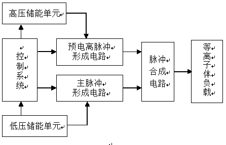
[0019] Such as figure 1 As shown, the new plasma sputtering coating device consists of a control system, a high-voltage energy storage unit, a low-voltage energy storage unit, a negative high-voltage pre-ionization pulse circuit, a low-voltage bipolar main pulse circuit, a pulse synthesis circuit and a plasma load. The control system is composed of touch screen, field programmable gate array (FPGA), programmable logic controller (PLC), isolation circuit and other peripheral circuits. The touch screen mainly realizes the setting of parameters such as the charging voltage of the high-voltage pre-ionization pulse and the high-power bipolar low-voltage main pulse, the output protection current, the pulse width of the optical signal, and the frequency of the optical signal, and controls the chargin...


PUM


Abstract

The invention discloses a novel plasma sputtering coating method. A device is composed of a control system, a high-voltage energy storage unit, a low-voltage energy storage unit, a negative polarity high voltage preionization pulse circuit, a double polarity low voltage main pulse circuit, a pulse fusion circuit and a plasma load. The design method of high voltage short pulses on plasma preionization and high power double polarity pulse magnetron sputtering is provided, the plasma load is subjected to multiple times of high voltage short pulse preionization and high power double polarity pulseelectric field treatment according to a certain repetition frequency, the time internal between negative polarity high voltage short pulses and high power positive and negative double polarity low voltage main pulses is reduced, and thus coupling between voltage pulses and the plasma load is enhanced, and the problem that the ionization moments of target materials are inconsistent is solved. Thewidth and voltage amplitude of negative polarity high voltage short pulses can be adjusted according to different sputtering target materials and plasma gases, the working pressure of gases in the magnetron sputtering device can be reduced, low-pressure sputtering coating is achieved, the deposition rate of particles is improved, and the surface roughness of a film is reduced.

Description

technical field [0001] The invention belongs to the research technical field of microelectronics, optical thin film and material surface treatment, and specifically relates to a novel plasma sputtering coating method and device, which uses negative polarity high-voltage short pulses to plasma pre-ionization and high-power bipolar low-voltage pulse magnetism. Controlled sputtering is used to solve the problems of low sputtering coating efficiency and improve the surface properties of thin films. Background technique [0002] In recent years, the coating preparation method mainly adopts physical vapor deposition (PVD) technology, which uses physical discharge processes such as glow discharge, arc discharge or thermal evaporation to deposit thin film coatings on the surface of the substrate. PVD technology mainly includes three types: vacuum evaporation, vacuum sputtering and ion plating. As a kind of vacuum sputtering, magnetron sputtering technology has become one of the wid...

Claims


Application Information

Patent Timeline
Patent Type & Authority Patents(China)
IPC IPC(8): C23C14/35
CPCC23C14/3485C23C14/354
Inventor 李波赵娟李洪涛叶超黄斌黄宇鹏张信齐卓筠欧阳艳晶李学华康传会
Owner INST OF FLUID PHYSICS CHINA ACAD OF ENG PHYSICS
Why Eureka
Try Eureka