Ternary polymer solar cell

A technology of solar cells and ternary polymers, applied in circuits, photovoltaic power generation, electrical components, etc., to achieve the effects of improving photoelectric conversion performance, inhibiting bimolecular charge recombination, and improving phase separation

Active Publication Date: 2018-11-16
NANJING UNIV OF POSTS & TELECOMM
View PDF12 Cites 3 Cited by
  • Summary
  • Abstract
  • Description
  • Claims
  • Application Information

AI Technical Summary

Problems solved by technology

To the best of our knowledge, the addition of small-molecule acceptors as "solid additives" in efficient all-polymer solar cells has not been reported, interesting interactions between small-molecule acceptors and polymeric materials are still unknown, and as The effect of combined polymer / molecular acceptors on the properties and performance of all-polymer solar cells requires further investigation

Method used


Image

  • Ternary polymer solar cell
  • Ternary polymer solar cell
  • Ternary polymer solar cell

Examples


Embodiment 1

[0046] Control group:

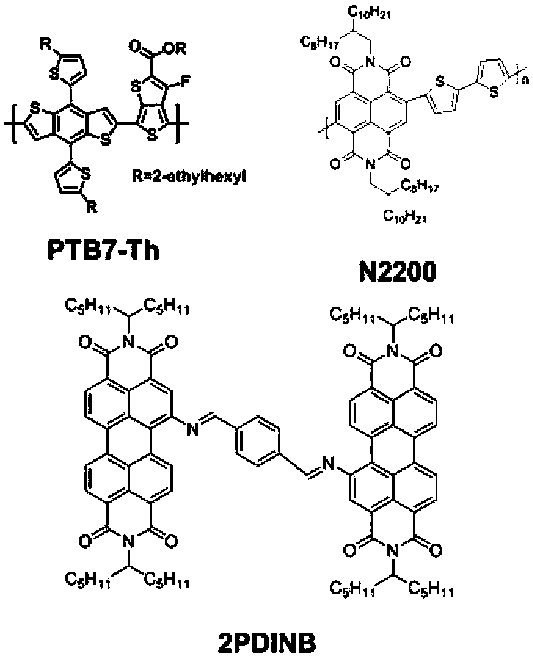
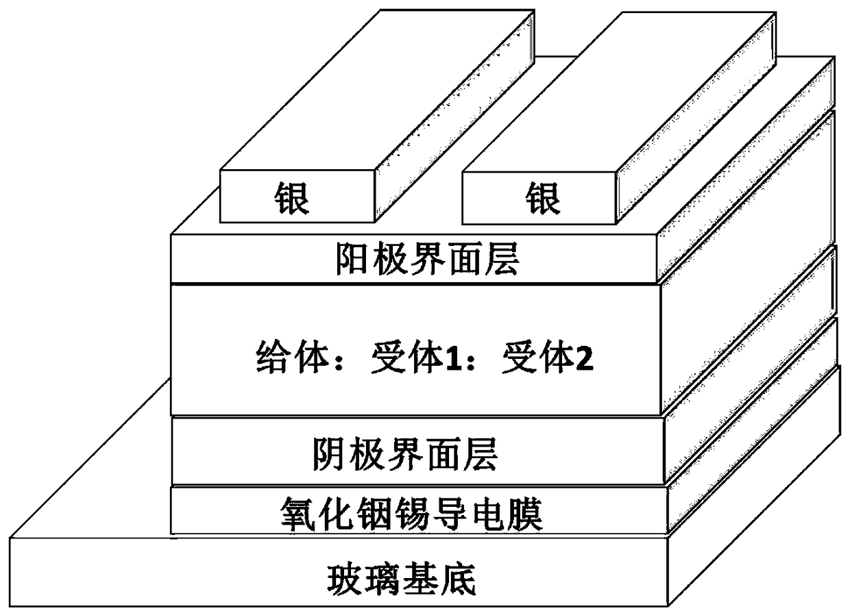
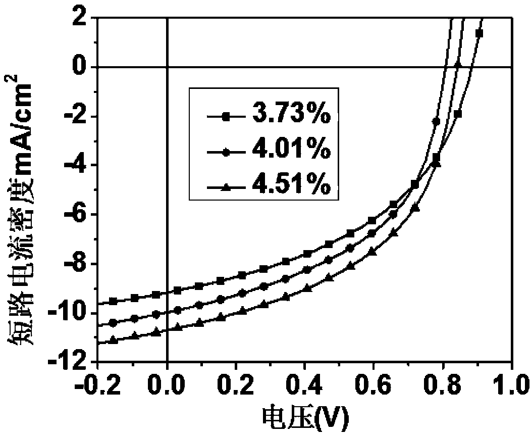
[0047] Clean the substrate composed of transparent substrate layer and transparent conductive cathode ITO with surface roughness less than 1nm, and blow dry with nitrogen after cleaning; spin-coat ZnO (4500rpm, 40s, 25nm) on the surface of transparent conductive cathode ITO to prepare cathode buffer layer, and the formed film was thermally annealed (200°C, 60min); the PTB7-Th:N2200 photoactive layer (2000rpm, 60s, 95nm) was prepared by spin coating on the cathode buffer layer, and the mass ratio was 1:1; Evaporation of MoO on the surface of the photoactive layer 3 (8nm); metal anode Ag (80nm) was vapor-deposited on the anode buffer layer. Under standard test conditions (AM1.5, 100mW / cm 2 ), the measured open circuit voltage of the device (V OC )=0.80V, short-circuit current (J SC )=11.2mA / cm 2 , fill factor (FF) = 0.45, photoelectric conversion efficiency (PCE) = 4.01%.

Embodiment 2

[0049] Clean the substrate composed of transparent substrate layer and transparent conductive cathode ITO with surface roughness less than 1nm, and blow dry with nitrogen after cleaning; spin-coat ZnO (4500rpm, 40s, 25nm) on the surface of transparent conductive cathode ITO to prepare cathode buffer layer, and the formed film was thermally annealed (200°C, 60min); the PTB7-Th:N2200:2PDINB photoactive layer (2000rpm, 60s, 95nm) was prepared by spin coating on the cathode buffer layer, and the mass ratio was 1:1 :0.1; evaporate MoO on the surface of the photoactive layer 3 (8nm); metal anode Ag (80nm) was vapor-deposited on the anode buffer layer. Under standard test conditions (AM 1.5, 100mW / cm 2 ), the measured open circuit voltage of the device (V OC )=0.80V, short-circuit current (J SC )=11.5mA / cm 2 , fill factor (FF) = 0.45, photoelectric conversion efficiency (PCE) = 4.07%.

Embodiment 3

[0051] Clean the substrate composed of transparent substrate layer and transparent conductive cathode ITO with surface roughness less than 1nm, and blow dry with nitrogen after cleaning; spin-coat ZnO (4500rpm, 40s, 25nm) on the surface of transparent conductive cathode ITO to prepare cathode buffer layer, and the formed film was thermally annealed (200°C, 60min); the PTB7-Th:N2200:2PDINB photoactive layer (2000rpm, 60s, 95nm) was prepared by spin coating on the cathode buffer layer, and the mass ratio was 1:1 :0.2; evaporate MoO on the surface of the photoactive layer 3 (8nm); metal anode Ag (80nm) was vapor-deposited on the anode buffer layer. Under standard test conditions (AM 1.5, 100mW / cm 2 ), the measured open circuit voltage of the device (V OC )=0.82V, short-circuit current (J SC )=12.1mA / cm 2 , fill factor (FF) = 0.45, photoelectric conversion efficiency (PCE) = 4.52%.


PUM

PropertyMeasurementUnit
Thicknessaaaaaaaaaa
Short circuit currentaaaaaaaaaa

Abstract

The invention discloses a ternary polymer solar cell, and belongs to the technical field of photovoltaics. An active layer of the polymer solar cell comprises two large-planar non-fullerene receptors,the cell employs an inversion structure, and the constitutes of the optical active layer comprise based on percent by weight: 41.6-50% of polymer electron donor, 0-50% of polymer electron receptor and 0-50% of non-fullerene perylene bisimide receptor. By adding the non-fullerene perylene bisimide receptor into the optical active layer, the spectrum absorption is expanded, phase separation is improved, dimolecular charge recombination can be suppressed, more effective charge generation and transmission are caused, so that the short-circuit current density of the device is improved, and the photoelectric conversion performance of the device is finally improved; and moreover, a new direction is provided for selection of the polymer non-fullerene receptor, and the ternary polymer solar cell formed by combining the two large-planar non-fullerene perylene bisimide receptors has the advantages of high photoelectric conversion performance, simple preparation process, short flow and low cost.

Description

technical field [0001] The invention belongs to the field of photovoltaic technology, and in particular relates to an organic polymer photovoltaic device, in particular to a ternary polymer solar cell. Background technique [0002] Organic solar cells (OSCs) are currently regarded as promising power generation technologies due to their superior advantages such as light weight, translucency, flexibility, and low-temperature fabrication process, which can be integrated into future flexible and wearable devices. To date, almost all of the highest efficiency organic solar cell devices have used conjugated polymers or small molecules as donor materials and fullerene derivatives as electron acceptors to form heterojunctions. However, fullerenes further limit the open-circuit voltage (V OC ) and short-circuit current density (J SC ), so it is not an ideal acceptor material. Furthermore, all-polymer solar cells, composed of polymer donor and polymer acceptor materials, possess su...

Claims


Application Information

Patent Timeline
IPC IPC(8): H01L51/42H01L51/46H01L51/48
CPCH10K85/621H10K30/451Y02E10/549
Inventor 赖文勇张建东杜斌黄维
Owner NANJING UNIV OF POSTS & TELECOMM
Why Eureka
Try Eureka