In-situ forming injectable hydrogel for bone-cartilage integrated restoration
A technology for cartilage repair and in situ molding, which is applied in prosthesis, drug delivery, tissue regeneration, etc. It can solve the problems of unseen injectable bone repair hydrogel materials, achieve high degree of substitution, increase cross-linking density, The effect of mild reaction conditions
- Summary
- Abstract
- Description
- Claims
- Application Information
AI Technical Summary
Problems solved by technology
Method used
Image
Examples
Embodiment 1
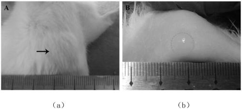
[0036] Add 3.0g of γ-polyglutamic acid, 75mg of 4-dimethylaminopyridine and 3.3g of glycidyl methacrylate to 100mL of phosphate buffer solution with pH=8.0, and stir at 1000rpm for 36h at room temperature to cross-link in the dark. The solution was transferred to a dialysis bag with a molecular weight cut-off of 3500, dialyzed with deionized water for 48 hours (substances with a molecular weight less than 3500 could be removed), and then centrifuged at 5000 rpm for 10 minutes using a centrifuge. The supernatant was taken out and freeze-dried to obtain methacrylylated γ-polyglutamic acid. Dissolve methacrylylated γ-polyglutamic acid and four-armed polyethylene glycol thiol in phosphate buffer at pH = 8.0 to obtain methacrylylated γ-polyglutamic acid with a mass fraction of 10%. solution and 10% four-arm polyethylene glycol mercapto solution. Mix the above solution according to the mass ratio of 1:4, 1:7, 1:10 and 1:13 (methacrylylated γ-polyglutamic acid: four-armed polyethyle...
Embodiment 2
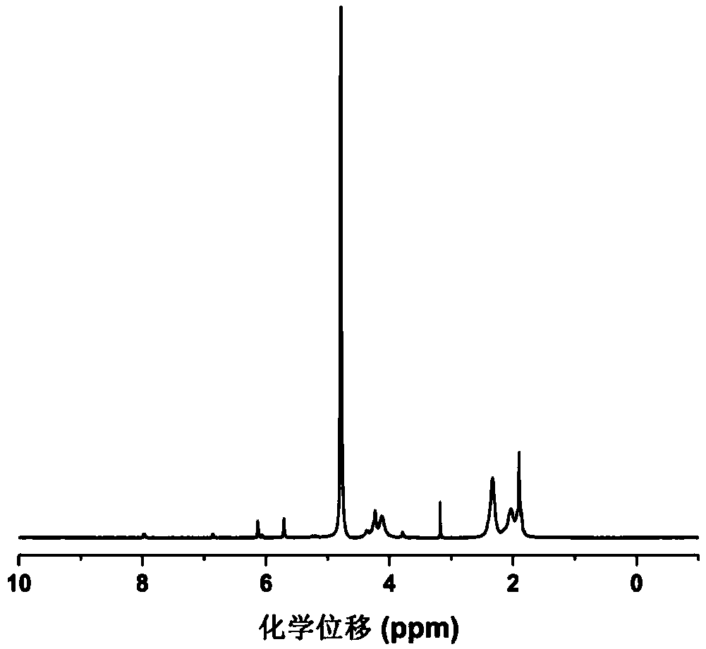
[0038] The methacrylylated γ-polyglutamic acid obtained in Example 1 was freeze-dried and ground into powder, and the substitution degree of the material was detected by proton nuclear magnetic resonance spectroscopy. Dissolve 5 mg of powder in 600 μL deuterated chloroform reagent, and detect its hydrogen spectrum with a 400 MHZ nuclear magnetic resonance instrument.
[0039] figure 1 It is the result of the methacrylylated γ-polyglutamic acid proton nuclear magnetic resonance spectrum experiment that embodiment 1 obtains, as seen in the figure, after GMA is grafted to the α-position carboxyl group of the γ-PGA side chain, 4.32ppm (H ,-CH-) spectrum peaks split; carbon-carbon double bond protons (2H,CH 2 =) characteristic peak, indicating that the grafting was successful, and the degree of substitution was 7.2%.
Embodiment 3
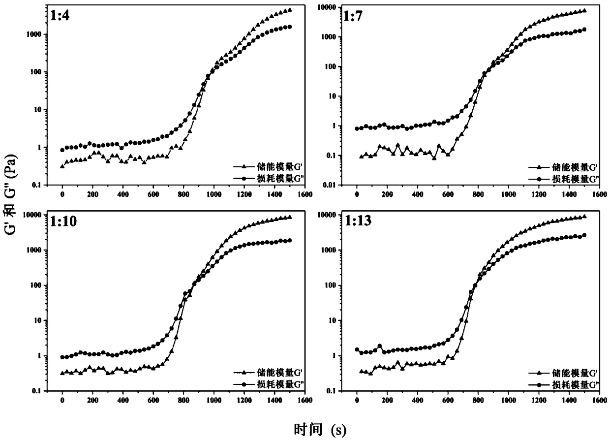
[0041] The injectable hydrogel precursor solution obtained in Example 1 was dropped onto the stage of the rheometer, and the rheological behavior of the precursor solution was detected in an oscillation mode. The detection temperature is 37°C, the oscillation frequency is 1HZ, and the test interval is 100μm.
[0042] figure 2 It is the result of the rheological experiment of the injectable hydrogel precursor solution obtained in Example 1. As can be seen from the figure, at 37°C, the phase transition times of IBRH1:4, IBRH1:7, IBRH1;10 and IBRH1:13 were 960s, 870s, 860s, and 780s, respectively.
PUM
 Abstract
Description
Claims
Application Information
 - R&D
- Intellectual Property
- Life Sciences
- Materials
- Tech Scout
- Unparalleled Data Quality
- Higher Quality Content
- 60% Fewer Hallucinations
Browse by: Latest US Patents, China's latest patents, Technical Efficacy Thesaurus, Application Domain, Technology Topic, Popular Technical Reports.
© 2025 PatSnap. All rights reserved.Legal|Privacy policy|Modern Slavery Act Transparency Statement|Sitemap|About US| Contact US: help@patsnap.com


