Optical fiber for maintaining vortex beam transmission, and manufacturing method of optical fiber

A vortex beam, optical fiber preform technology, applied in the direction of multi-layer core/clad optical fiber, cladding optical fiber, optical waveguide light guide, etc., can solve the problems of limited transmission distance, OAM beam crosstalk, etc. The effect of low price and low bending loss

Inactive Publication Date: 2018-12-28
SHANGHAI UNIV
View PDF9 Cites 9 Cited by
  • Summary
  • Abstract
  • Description
  • Claims
  • Application Information

AI Technical Summary

Problems solved by technology

However, in free space, the propagation of vortex beams is easily affected by adverse environments such as atmospheric turbulence, and crosstalk is prone to occur between OAM beams, which limits its transmission distance.

Method used


Image

  • Optical fiber for maintaining vortex beam transmission, and manufacturing method of optical fiber
  • Optical fiber for maintaining vortex beam transmission, and manufacturing method of optical fiber
  • Optical fiber for maintaining vortex beam transmission, and manufacturing method of optical fiber

Examples


preparation example Construction

[0036] A method for preparing an optical fiber for vortex beam transmission and maintenance, which is used to prepare the above-mentioned optical fiber for vortex beam transmission and maintenance, comprising the following steps:

[0037] Step 1, using a deposition method to deposit an inner cladding 2 on the fiber core 1, and then depositing an outer cladding 3 on the inner cladding 2 to form an optical fiber preform to be sintered;

[0038] Step 2, sintering the optical fiber preform at high temperature to form an optical fiber preform to be drawn;

[0039] In step 3, the optical fiber preform is drawn, and at the same time rotated along the axis of the optical fiber preform so that the pitch range is within 0.05-10 mm, and the preparation of the optical fiber is completed.

[0040] In step 1, the deposition method is one or any of improved chemical vapor deposition, furnace chemical vapor deposition, plasma chemical vapor deposition, external vapor deposition, axial vapor d...

Embodiment 1

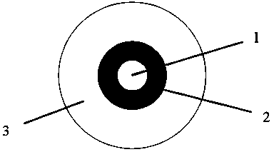
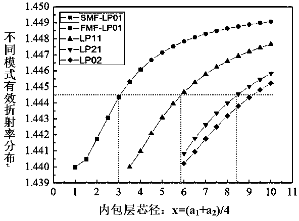
[0042] Such as figure 1 As shown, an optical fiber for vortex beam transmission includes a core 1 with a low refractive index distribution, a ring-shaped inner cladding 2 that surrounds the core 1 and has a certain refractive index distribution, and an outer cladding composed of pure silica Layer 3, the core 1 and inner cladding 2 at a cutoff wavelength greater than 1100nm, only supports LP 01 and LP 11 die, and the LP 01 and LP 11 The refractive index distribution between different modes is as follows image 3 shown. At the same time, the spinning optical fiber with a ring structure with a certain refractive index distribution is prepared by the spinning drawing process, and has different pitch structures, such as Figure 5 As shown, choose Pitch=2.5mm here.

[0043] The optical fiber has a step-type refractive index distribution, wherein the core 1 is a quartz material doped with a small amount of germanium dioxide, the inner cladding 2 is made of fluorine-doped or bor...

Embodiment 2

[0045] see figure 2 , image 3 and Figure 4 , the manufacturing steps of an optical fiber applied to vortex beam transmission are as follows:

[0046] Firstly, a germanium-doped cladding layer with high refractive index distribution is sequentially deposited by an improved chemical vapor deposition method, and then a small amount of fluoride or boride quartz inner cladding layer is deposited, or pure quartz is used as the core layer.

[0047] Through chemical vapor deposition technology, high-temperature sintering into a solid or hollow optical fiber preform with a certain pore structure, the core diameter and outer diameter of the preform are 2mm and 15mm respectively;

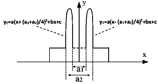
[0048] The optical fiber preform is drawn into an optical fiber in a drawing tower, and the diameters of the core 1 and the inner cladding 2 are respectively a 1 and a 2 , and rotate along the axis of the optical fiber preform while drawing, and the pitch here is 1.5 mm. Finally, the spinning fiber is ...


PUM


Abstract

The invention relates to an optical fiber for maintaining vortex beam transmission, and a manufacturing method of the optical fiber. The refractive indexes of all cladding layers inside the optical fiber are reasonably configured, and in combination with a rotary wire drawing technology, a spun optical fiber having distributed refractive indexes and applied to a ring structure for maintaining transmission of vortex beam with orbital angular momentum is provided; and the optical fiber has the characteristics of low loss, low bending loss, relatively low chromatic dispersion, relatively large effective area, simple structure, low price, easy for industrial production and the like, is suitable for mode division multiplexing and space division multiplexing systems in optical communication, canbe applied to optical fiber laser devices and optical fiber sensors to perform vortex beam transmission and generation, and has good popularization and application values.

Description

technical field [0001] The invention belongs to the technical field of optical fiber transmission, and in particular relates to an optical fiber used for vortex beam transmission and maintenance and a preparation method thereof. Background technique [0002] With the continuous acceleration of the informatization process of modern society and the continuous increase of bandwidth-consuming services, the capacity requirements of information transmission systems continue to increase. Optical fiber communication technology, as the basic communication infrastructure in the world today, supports the transmission of voice, video and data around the world, and is facing the inevitable rapid growth of data transmission capacity. In the past few years, the growth rate of my country's optical network data demand has reached as high as 200%, and higher and higher requirements have been placed on the transmission capacity of optical networks. In order to improve the information transmiss...

Claims


Application Information

Patent Timeline
Patent Type & Authority Applications(China)
IPC IPC(8): G02B6/036G02B6/032G02B6/02
CPCG02B6/02009G02B6/032G02B6/03622
Inventor 文建湘王廷云董艳华邢建飞庞拂飞陈振宜
Owner SHANGHAI UNIV
Why Eureka
Try Eureka