AI technical title is built by Patsnap AI team. It summarizes the technical point description of the patent document.
An electroluminescent device, organic technology, applied in the direction of electric solid devices, electrical components, semiconductor devices, etc., can solve the problem of low light output efficiency
Active Publication Date: 2019-01-18
CHANGCHUN HYPERIONS TECH CO LTD
View PDF5 Cites 6 Cited by
Summary
Abstract
Description
Claims
Application Information
AI Technical Summary
This helps you quickly interpret patents by identifying the three key elements:
Problems solved by technology
Method used
Benefits of technology
Problems solved by technology
[0004] Purpose of the invention: In view of the above problems, the purpose of the present invention is to provide an organic electroluminescent device, which solves the problem of low light extraction efficiency of the current organic electroluminescent device
Method used
Image
Click on the blue label to locate the original text in one second.
Reading with bidirectional positioning of images and text.
Examples
Embodiment 1
[0169] Synthesis Example 1: Preparation of Compound I-1
[0170]
[0171] Add 10,10-Dimethylanthrone (6.7g, 30mmol) to the round bottom flask, add toluene to dissolve it, add p-toluenesulfonyl hydrazide (8.4g, 45mmol) to the solution, at 80℃ After reacting for 2h under the conditions, add 4-boronic acidtriphenylamine (13.0g, 45mmol) and K 2 CO 3 (12.4g, 90mmol), reflux reaction for 5h, the reaction solution was cooled to room temperature, the reaction solution was washed with deionized water, the organic phase was dried, concentrated, and column chromatography to obtain compound I-1 (10.8g, 80%). Mass spectrum m / z: theoretical value: 451.61; measured value: 453.79. Theoretical element content (%) C 34 H 29 N: C, 90.43; H, 6.47; N, 3.10; Measured element content (%): C, 90.41; H, 6.53; N, 3.07. The above results confirm that the obtained product is the target product.
Embodiment 2
[0172] Synthesis Example 2: Preparation of Compound I-2
[0173]
[0174] The 4-boronic acidtriphenylamine in Example 1 was replaced with equimolar 4-(dibiphenyl-4-amino)phenylboronic acid, and the other steps were the same as the synthesis of Example 1, to obtain compound I-2 (15.2g ,84%). Mass spectrum m / z: theoretical value: 603.81; measured value: 605.94. Theoretical element content (%) C 46 H 37 N: C, 91.50; H, 6.18; N, 2.32; Measured element content (%): C, 91.45; H, 6.25; N, 2.30. The above results confirm that the obtained product is the target product.
Embodiment 3
[0175] Synthesis Example 3: Preparation of Compound I-11
[0176]
[0177] Add 2-bromotriphenylene (11.5g, 37.5mmol), 2-triphenylamine (9.1g, 37.5mmol), t-BuONa (5.4g, 56.25mmol), Pd to the round-bottomed flask in sequence. 2 (dba) 3 (0.686g, 0.75mmol) and toluene (200mL) deoxygenated ultrasonically, followed by P(t-Bu) dissolved in toluene (3mL) 3 (0.36g, 1.8mmol), reflux overnight under the protection of nitrogen. After the reaction solution was cooled to room temperature, it was treated with ethyl acetate and water, and the obtained organic layer was treated with MgSO 4 After drying and evaporating the solvent under reduced pressure, the crude product was subjected to column chromatography using silica gel as a stationary phase and dichloromethane / hexane as eluent to obtain compound D1 (11.4 g, 65%).
[0178] Under the protection of nitrogen, compound D1 (11.8g, 25mmol), 4-iodophenylboronic acid (6.2g, 25.0mmol), t-BuONa (4.2g, 37.5mmol), Pd were sequentially added to the flask un...
PUM
Abstract
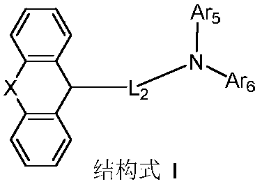
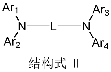
The invention discloses an organic electroluminescent device, which relates to the technical field of organic electroluminescent display. The organic electroluminescent device including the anode, anorganic layer, a cathode and a light extraction layer; the organic layer is located between the anode and the cathode, the organic layer includes a light emitting layer, The light extraction layer islocated on a side of the cathode away from the anode, the light extraction layer sequentially comprising a first light extraction layer and a second light extraction layer from a side close to the cathode, the first light extraction layer containing a compound represented by Formula I, and the second light extraction layer containing a compound represented by Formula II. The organic electroluminescent device of the invention not only improves the transmittance of the cathode surface, but also greatly reduces the influence of the surface plasma effect and the waveguide effect, and improves thelight-emitting efficiency of the organic electroluminescent device because of the low light absorption coefficient and the high refractive index of the materials used in the first light-emitting layerand the second light-emitting layer.
Description
Technical field [0001] The present invention relates to the technical field of organic electroluminescence display, in particular to an organic electroluminescence device. Background technique [0002] Organic Light-Emitting Diode (OLED) refers to a device in which organic photoelectric materials emit light under the action of electric current or electric field, which can directly convert electrical energy into light energy. In recent years, OLED has received more and more attention as a new generation of flat panel display and solid-state lighting technology. Compared with liquid crystal display technology, OLED is increasingly used in display and lighting fields for its low power consumption, active light emission, fast response speed, high contrast, no viewing angle limit, and flexible display. [0003] However, because the OLED is affected by the waveguide effect and the surface plasmon effect, only about 20% of the light can escape the device, and about 80% of the light is co...
Claims
Application Information
Patent Timeline
Application Date:The date an application was filed.
Publication Date:The date a patent or application was officially published.
First Publication Date:The earliest publication date of a patent with the same application number.
Issue Date:Publication date of the patent grant document.
PCT Entry Date:The Entry date of PCT National Phase.
Estimated Expiry Date:The statutory expiry date of a patent right according to the Patent Law, and it is the longest term of protection that the patent right can achieve without the termination of the patent right due to other reasons(Term extension factor has been taken into account ).
Invalid Date:Actual expiry date is based on effective date or publication date of legal transaction data of invalid patent.

