Smoke purifying and waste heat utilizing system of waste incineration power plant

A technology for flue gas purification and waste incineration, applied in incinerators, combustion methods, gas treatment, etc., can solve the problems of increasing dioxin-like air pollutants, failing to obtain sufficient combustion, and reducing the effect of purification, and achieves good results. Thermal conductivity, low cost, good isothermal effect

Active Publication Date: 2019-03-01
QUJING YUNDIAN TOUXIN ENERGY POWER GENERATION
View PDF8 Cites 7 Cited by
  • Summary
  • Abstract
  • Description
  • Claims
  • Application Information

AI Technical Summary

Problems solved by technology

The most well-studied toxic dioxins are 17 homologue isomer monomers (congenor) whose 2-, 3-, 7-, and 8-positions are substituted by chlorine atoms, among which 2,3,7,8-tetrachloro Dibenzo-p-dioxin (2,3,7,8-TCDD) is currently the most toxic dioxin monomer among all known compounds (oral LD ​​is only 1ug / kg by weight), And there are also a variety of toxic effects including extremely strong carcinogenicity (rat liver cancer-causing dose of 10 μg / g by body weight) and extremely low dose of environmental endocrine disruption. From the above, dioxins in high-temperature flue gas The treatment and control of air pollutants is crucial to human health and environmental protection, and these flue gases often have waste heat with high heat. If they are directly discharged, they will cause a lot of energy loss on the one hand, and on the other hand It will cause serious pollution to the surrounding environment. Therefore, the flue gas generated by waste incineration generally needs to be purified and discharged.
In the existing technology, waste heat boilers, pickling neutralization equipment, bag dust removal equipment and waste heat recovery equipment are usually used for purification treatment of flue gas. Although they can meet the needs of use to a certain extent, there are the following deficiencies: 1. During the combustion process of the incinerator, due to the poor control of the process conditions, the dioxin-like compounds entrained in the waste raw materials were not completely decomposed, resulting in the dioxin-like compounds entering the high-temperature flue gas, and more seriously, the dioxin-like compounds in the raw materials The entrained chlorine-containing organic compounds are not fully burned, resulting in a large amount of dioxin precursors such as chlorophenols and polychlorinated biphenyls, which are carried by the smoke into the high-temperature flue gas treatment system. Second, in the high-temperature flue gas treatment system, waste heat Boiler heat exchange, pickling neutralization and equipment washing, bagging equipment and other treatment processes, due to the long treatment time and the operating temperature falling within the temperature range of 250-680 °C where dioxins are easily generated, are precursors in high-temperature flue gas. Dioxins are synthesized at 250-500°C, and chlorophenols, chlorophenol groups, various organic compounds, and organic groups are synthesized at 580-680°C, which provides conditions for the re-synthesis of dioxin-like pollutants , which greatly increases the dioxin-like air pollutants in the high-temperature flue gas. Third, after the existing purification equipment is used for a certain period of time, its purification effect will be significantly reduced, and the cost of post-processing and maintenance is relatively high.

Method used


Image

  • Smoke purifying and waste heat utilizing system of waste incineration power plant
  • Smoke purifying and waste heat utilizing system of waste incineration power plant

Examples


Embodiment Construction

[0028] The present invention will be further described below in conjunction with the examples and accompanying drawings, but the present invention is not limited in any way. Any transformation or replacement based on the teaching of the present invention belongs to the protection scope of the present invention.

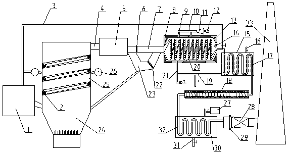
[0029] Such as Figure 1~2As shown, the flue gas purification and waste heat utilization system of the waste incineration power plant includes an incinerator body 24, a steam turbine 11, a generator 12, a flue gas purification treatment device, and a chimney 33. The incinerator body 24 is provided with a garbage inlet Feeder 1, secondary air pipe 26 and high-temperature flue gas outlet 4, the middle and upper part of the incinerator body 24 is provided with a spiral convex ring 2, and a spiral guide is formed between the spiral convex ring 2 and the inner wall of the incinerator body 24 Groove 25, the flue gas that the rubbish incineration in the incinerator body 24 p...


PUM


Abstract

The invention discloses a smoke purifying and waste heat utilizing system of a waste incineration power plant. The smoke purifying and waste heat utilizing system comprises an incinerator body, a steam turbine, a power generator, a smoke purifying treatment device and a smoke discharge chimney. The smoke purifying treatment device comprises a pipeline combustor, a steam generator, a waste heat recoverer, a smoke decomposer, a washing tank and an adsorption purifier which are sequentially arranged from a high-temperature smoke outlet and the smoke discharge chimney. The smoke discharge pipe isarranged between the pipeline combustor and the steam generator. A particle collecting pipe is arranged on the lower side of the smoke discharge pip. A spiral smoke pipe is arranged in the steam generator. A heat pipe is arranged in the waste heat recoverer. An outer cylinder, an inner cylinder and a decomposition ball are arranged in the smoke decomposer. An inner electrode is arranged on the inner side of the inner cylinder. An outer electrode is wound on the outer surface of the outer cylinder. A washing pipe is arranged in the washing tank. The adsorption purifier is filled with adsorptionfiller. By means of the system, the combustion state is improved, combustion efficiency is improved, the dioxin content is reduced, and the waste heat recovery efficiency is improved.

Description

technical field [0001] The invention belongs to the technical field of industrial waste gas treatment, and in particular relates to a flue gas purification and waste heat utilization system of a waste incineration power plant. Background technique [0002] At present, in the waste incineration power generation operation, after the waste incinerator incinerates the waste, it often produces dioxin gas containing a large amount of acid pollutants, heavy metal ion particles, solid dust and peculiar smell. Dioxin usually refers to a gas with similar structure and A group of polychlorinated substituted planar aromatic hydrocarbons with physical and chemical properties, belonging to chlorinated oxygen-containing tricyclic aromatic hydrocarbons, including 75 polychlorinated dibenzo-one-to-one dioxins and 135 polychlorinated dibenzofuran , abbreviated as PCDD / Fs. The most well-studied toxic dioxins are 17 homologue isomer monomers (congenor) whose 2-, 3-, 7-, and 8-positions are sub...

Claims


Application Information

Patent Timeline
IPC IPC(8): B01D46/12B01D46/02B01D53/32B01D53/70B01D53/18B01D53/14F23G7/06
CPCB01D46/02B01D46/12B01D53/1456B01D53/1468B01D53/18B01D53/323B01D53/70B01D2253/102B01D2253/106B01D2253/108B01D2253/1124B01D2257/2064B01D2258/0283B01D2258/0291F23G7/06Y02E20/12
Inventor 刘银锟黄照良黄河评张政委殷智华张旺
Owner QUJING YUNDIAN TOUXIN ENERGY POWER GENERATION
Why Eureka
Try Eureka