Perovskite solar cell and preparation method thereof
What is AI technical title?
AI technical title is built by Patsnap AI team. It summarizes the technical point description of the patent document.
A solar cell and perovskite technology, applied in the field of solar cells, to achieve the effects of slowing down hysteresis, improving efficiency and improving crystal grains
Active Publication Date: 2019-04-26
KUNSHAN GCL OPTOELECTRONIC MATERIAL CO LTD
View PDF7 Cites 10 Cited by
Summary
Abstract
Description
Claims
Application Information
AI Technical Summary
This helps you quickly interpret patents by identifying the three key elements:
Problems solved by technology
Method used
Benefits of technology
Problems solved by technology
[0005]
Based on this, it is necessary to address the problem of how to improve the efficiency of perovskite devices, and provide a perovskite solar cell capable of improving the efficiency of perovskite devices and a preparation method thereof
Method used
Image
Click on the blue label to locate the original text in one second.
Reading with bidirectional positioning of images and text.
Examples
preparation example Construction
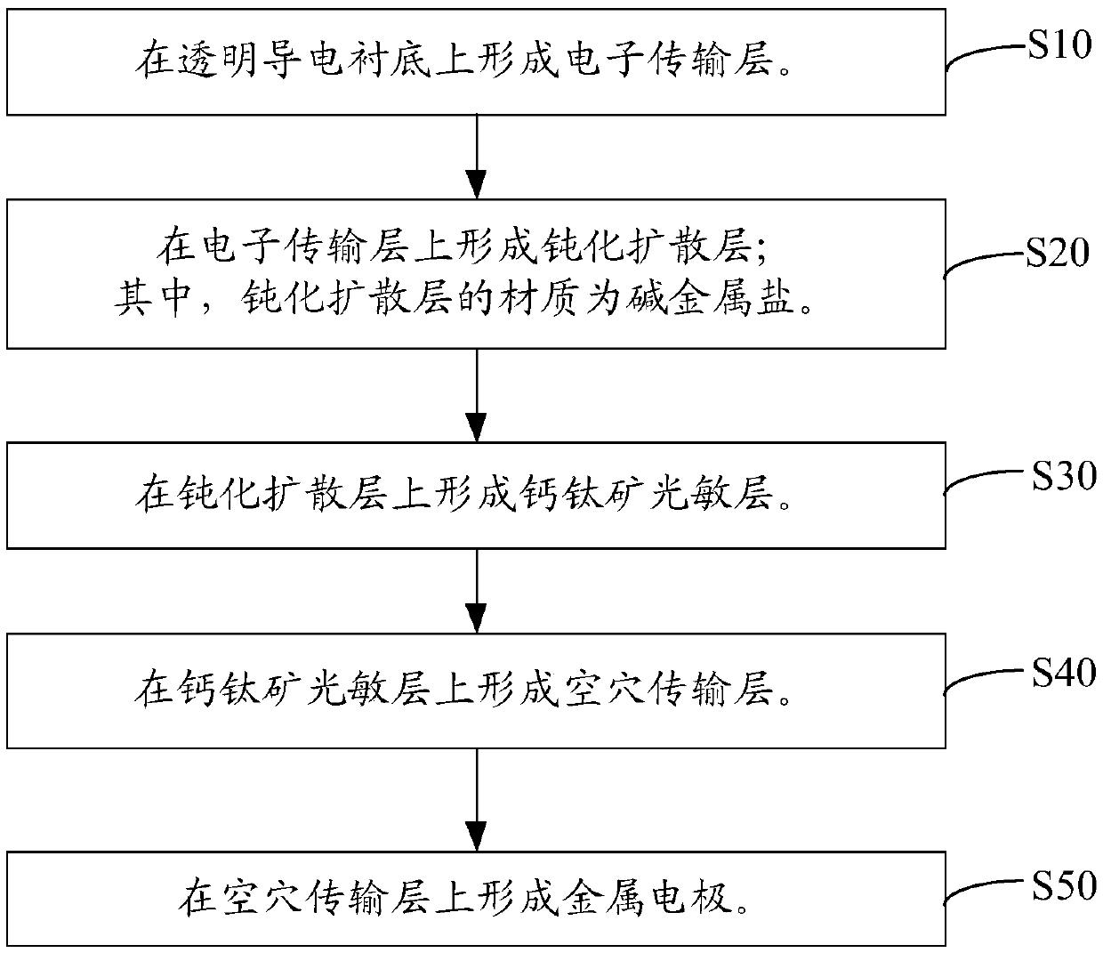
[0059] See image 3 , the preparation method of the perovskite solar cell of one embodiment of the present invention comprises the following steps:
[0062] S20, forming a passivation diffusion layer on the electron transport layer; wherein, the material of the passivation diffusion layer is alkali metal salt.
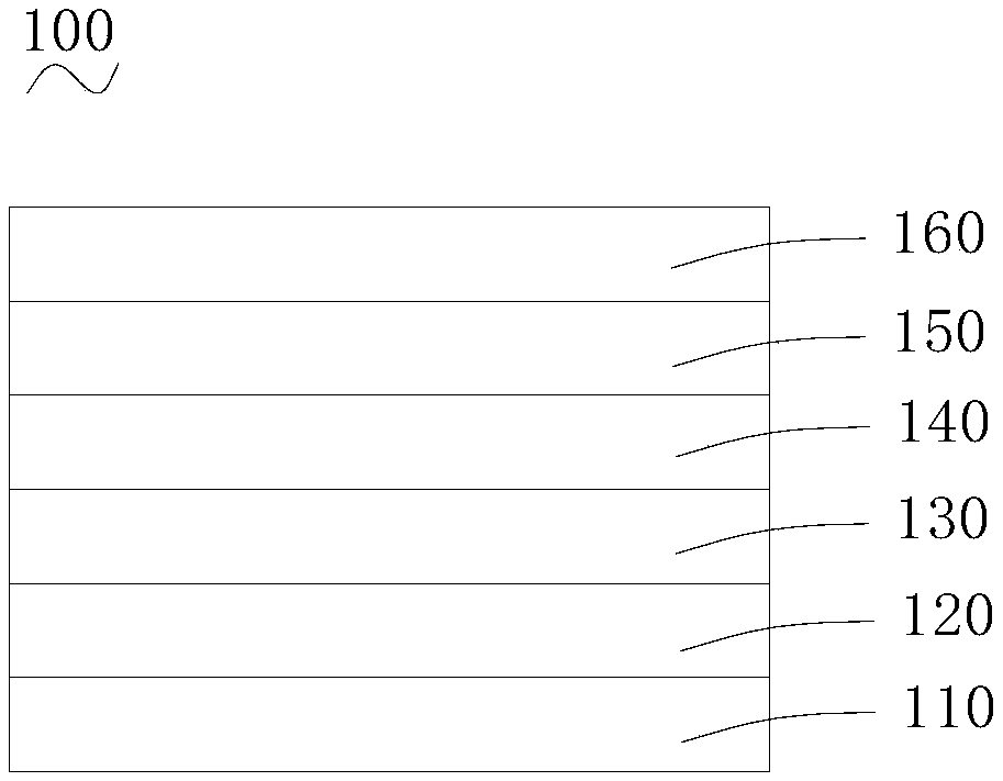
[0063] Please also see Figure 4 , a passivation diffusion layer 130 is formed on the electron transport layer 120 .
[0064] Preferably, the operation of forming a passivation diffusion layer on the electron transport layer i...
Embodiment 1
[0092] 1. Spin-coat 0.1M tinoxidequantum dot solution on a transparent conductive substrate, the spin-coating conditions are: 3000rpm, 1000m / s 2 , 30s, and then annealed at 100° C. for 10 minutes, then raised to 200° C. and annealed for 30 minutes to obtain a tinoxide electron transport layer.
[0093] 2. Spin-coat 30mg / ml KCL aqueous solution on the tinoxide electron transport layer, the spin-coating conditions are: 5000rpm, 2500m / s 2 , 30s, and then annealed at 120° C. for 15 minutes to obtain an alkali metal salt passivation diffusion layer.
[0094] 3. Spin-coat the 1.5M perovskite solution on the passivation diffusion layer, the spin-coating conditions are: 3000rpm, 1500m / s 2 , 7s, get a relatively uniform perovskite liquid film (wet film) after spin coating, then immediately put it into the air pumping device, pump air for about 30s, remove most of the solvent, and get a relatively dry and completely crystallized perovskite thin film, and then make the perovskite t...
Embodiment 2
[0098] The difference between Example 2 and Example 1 is that the annealing method of the perovskite film in step 3 is not directly contacted with the heating plate for heating, but a conventional heating method, that is, the perovskite film faces upward and the transparent conductive substrate faces downward Contact heating plate for heating.
technical field [0001] The invention relates to the technical field of solar cells, in particular to a perovskite solar cell and a preparation method thereof. Background technique [0002] Perovskites are formed from organic halide and metalhalide salts to form ABX 3 Crystal structure, A is generally methylamino (CH 3 NH 3 ), B is a divalent metal ion (such as Pb 2+ or Sn 2+ ), X is chlorine, bromine, iodine and other halogen atoms, the most common perovskite material is lead iodidemethylamine (CH 3 NH 3 PB 3 ), its band gap is about 1.5eV, and its extinction coefficient is high. A thin film with a thickness of several hundred nanometers can fully absorb sunlight below 800nm. Perovskite solar cells include many kinds of structures: mesoscopic structure, mesoscopic superstructure, planar n-i-p type and planar p-i-n type structure. [0003] Perovskite cells have become a research hotspot due to their excellent photoelectric properties. Perovskite cells generally inc...
Claims
Application Information
Patent Timeline
Application Date:The date an application was filed.
Publication Date:The date a patent or application was officially published.
First Publication Date:The earliest publication date of a patent with the same application number.
Issue Date:Publication date of the patent grant document.
PCT Entry Date:The Entry date of PCT National Phase.
Estimated Expiry Date:The statutory expiry date of a patent right according to the Patent Law, and it is the longest term of protection that the patent right can achieve without the termination of the patent right due to other reasons(Term extension factor has been taken into account ).
Invalid Date:Actual expiry date is based on effective date or publication date of legal transaction data of invalid patent.

