No in boiler flue gas x Partial redox removal method and removal device

A boiler flue gas removal technology, which is applied in separation methods, chemical instruments and methods, gas treatment, etc., can solve the problems of poor reduction effect, hindering industrial application, and difficulty in controlling the degree of oxidation, etc., and achieves strong high temperature resistance and corrosion resistance , Visible light catalytic activity is strong, the effect of reducing oxidation residence time

Active Publication Date: 2021-10-22
山东默锐环境产业股份有限公司
View PDF0 Cites 0 Cited by
  • Summary
  • Abstract
  • Description
  • Claims
  • Application Information

AI Technical Summary

Problems solved by technology

After most of NO is oxidized (also known as NO full oxidation), it is absorbed by lye. To meet the discharge standard, it needs to consume more oxidant, which is expensive and hinders industrial application.
There are two ways to reduce the cost of this technology: one is to choose cheap oxidants (such as H 2 o 2 or NaClO), but the oxidation effect of NO is limited, and auxiliary means such as catalysis are needed, and the development of catalysts has not been able to break through SO 2 and water vapor poisoning lead to catalytic deactivation; the second is to implement quantitative oxidation of NO (i.e. partial oxidation of NO) instead of pursuing high NO x degree of oxidation (NO x Medium NO 2 ratio) to save oxidants, and then control NO and NO by adjusting the degree of oxidation 2 The ratio of urea, sodium sulfite, and sodium bisulfite is used as a reducing agent for reduction and denitrification, which reduces costs and ensures high denitrification efficiency. However, this technology has the problem that the degree of oxidation is difficult to control and the reduction effect is poor.
[0004] It has been 50 years since Japanese scientists Fujishima and Honda discovered photocatalysis, and the development of its application is still going on. Among many photocatalysts, TiO 2 Photocatalyst has excellent properties such as high oxidation activity, stable activity, and not easy to decompose itself. However, so far, its application in the oxidation treatment of exhaust gas is still greatly restricted. At present, there are still several problems restricting the application of photocatalytic technology in exhaust gas treatment. The industrial application of the catalyst, including the low quantum yield of the catalyst, the low utilization rate of visible light, and the difficulty of separating nanocatalysts, etc.

Method used


Image

  • No in boiler flue gas  <sub>x</sub> Partial redox removal method and removal device
  • No in boiler flue gas  <sub>x</sub> Partial redox removal method and removal device
  • No in boiler flue gas  <sub>x</sub> Partial redox removal method and removal device

Examples


Embodiment 1

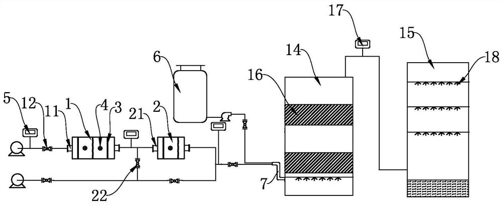
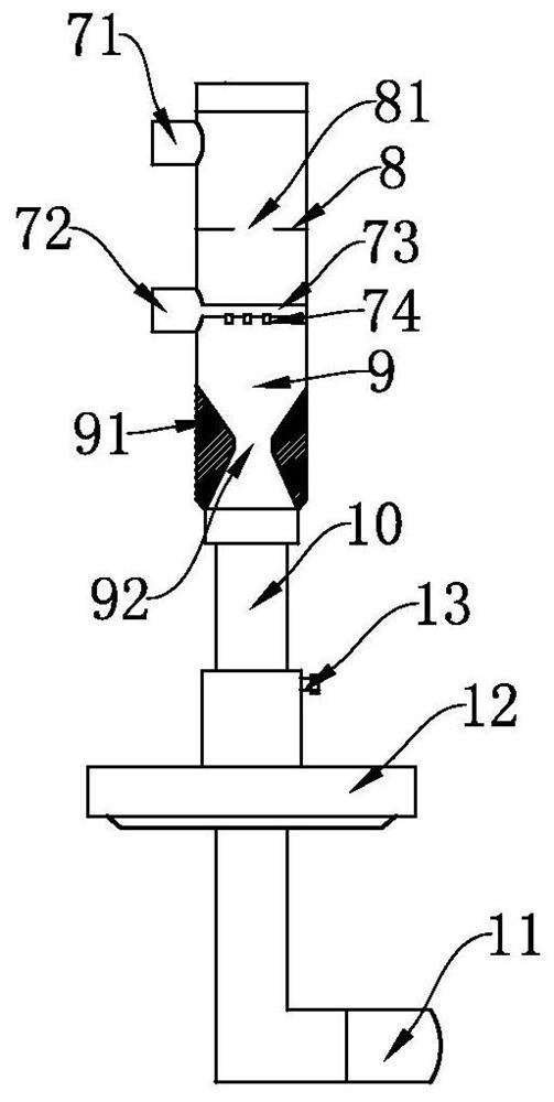
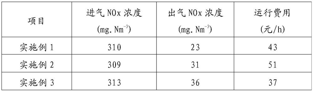
[0053] (1) Photocatalytic oxidation: The boiler flue gas enters the two-stage photocatalytic oxidation device in series respectively, and the photocatalytic oxidation is carried out in sequence. The first-stage photocatalytic oxidation device is equipped with three mesh plates loaded with photocatalysts along the gas flow direction ; In the second-stage photocatalytic oxidation device, there are two loaded nano-Pd / TiO along the direction of gas flow. 2 50W LED lights are arranged between the mesh panels. The residence time of boiler flue gas in the first-stage photocatalytic oxidation device is 15s; the residence time of boiler flue gas in the second-stage photocatalytic oxidation device is 10s. NO in the flue gas after the first stage photocatalytic oxidation X The degree of oxidation is 75%, and the NO in the flue gas after the second stage photocatalytic oxidation X The degree of oxidation is 50%. According to the inlet oxidation degree and outlet gas oxidation degree of...

Embodiment 2

[0058] (1) Photocatalytic oxidation: The boiler flue gas enters the two-stage photocatalytic oxidation device in series respectively, and the photocatalytic oxidation is carried out in sequence. The first-stage photocatalytic oxidation device is equipped with three mesh plates loaded with photocatalysts along the gas flow direction ; In the second-stage photocatalytic oxidation device, there are two loaded nano-Pd / TiO along the direction of gas flow. 2 50W LED lights are arranged between the mesh panels. The residence time of boiler flue gas in the first-stage photocatalytic oxidation device is 18s; the residence time of boiler flue gas in the second-stage photocatalytic oxidation device is 12s. NO in the flue gas after the first stage photocatalytic oxidation X The degree of oxidation is 80%, and the NO in the flue gas after the second stage photocatalytic oxidation X The degree of oxidation is 49%. According to the inlet oxidation degree and outlet gas oxidation degree of...

Embodiment 3

[0063] (1) Photocatalytic oxidation: The boiler flue gas enters the two-stage photocatalytic oxidation device in series respectively, and the photocatalytic oxidation is carried out in sequence. The first-stage photocatalytic oxidation device is equipped with three mesh plates loaded with photocatalysts along the gas flow direction ; In the second-stage photocatalytic oxidation device, there are two loaded nano-Pd / TiO along the direction of gas flow.2 50W LED lights are arranged between the mesh panels. The residence time of boiler flue gas in the first-stage photocatalytic oxidation device is 10s; the residence time of boiler flue gas in the second-stage photocatalytic oxidation device is 8s. NO in the flue gas after the first stage photocatalytic oxidation X The degree of oxidation is 70%, and the NO in the flue gas after the second stage photocatalytic oxidation X The degree of oxidation is 50%. According to the inlet oxidation degree and outlet gas oxidation degree of ea...


PUM


Abstract

The invention discloses a method for reducing NO in boiler flue gas X The partial redox removal method and removal device include the following steps: (1) respectively enter the boiler flue gas into at least two photocatalytic oxidation devices connected in series, and perform photocatalytic oxidation in sequence, and the flue gas after the photocatalytic oxidation is completed NO X The degree of oxidation is 45-50%. (2) The flue gas and reducing liquid after the catalytic oxidation are completed are instantly pressurized and the flue gas is atomized in the mixing feeder to become atomized flue gas. (3) The atomized flue gas enters the reduction and denitration tower, and is discharged from the top after being reduced and denitrated by the denitration catalytic packing. (4) The flue gas from the top of the reduction denitrification tower enters the desulfurization tower, and is discharged after being desulfurized by spraying desulfurization liquid. In the present invention, the boiler flue gas enters at least two stages of photocatalytic oxidation devices connected in series, and the photocatalytic oxidation is carried out sequentially, thereby improving the photocatalytic oxidation speed, controlling the oxidation degree of each stage accurately, and ensuring a good reduction and denitrification effect.

Description

technical field [0001] The invention relates to the technical field of industrial waste gas treatment, in particular to a NO X Redox removal technology. Background technique [0002] At present, the nitrogen oxides NO emitted into the atmosphere by the industrial production process x NO and NO 2 Mainly, they are the main precursors of acid rain and smog, which seriously endanger the ecological environment and human health. Nitric oxide (NO) in boiler flue gas accounted for total nitrogen oxides (NO x ) above 95%, NO is not easily absorbed in water or lye, and nitrogen dioxide (NO 2 ) is easily soluble in water and easy to remove, so the main problem of flue gas denitrification is to remove NO. [0003] According to NO and NO in flue gas 2 Different denitrification methods can be used for different content: NO 2 Main NO x Exhaust gas is mainly absorbed and purified; while NO mainly consists of NO x Exhaust gases can reduce NO to harmless N 2 , this process is divide...

Claims


Application Information

Patent Timeline
Patent Type & Authority Patents(China)
IPC IPC(8): B01D53/75B01D53/56B01D53/78B01D53/50
CPCB01D53/502B01D53/56B01D53/75B01D2251/304B01D2255/1023B01D2255/20707B01D2255/802B01D2258/0283
Inventor 徐永生王志孝杨建伟刘玉辉孙广金魏雪花张海涛王彦玲
Owner 山东默锐环境产业股份有限公司
Why Eureka
Try Eureka