A three-dimensional ultrasound imaging system

An imaging system and three-dimensional ultrasound technology, which is used in material analysis, instruments, and measurement devices using sonic/ultrasonic/infrasonic waves, can solve the problems of affecting the measurement effect, low cost, and low spatial resolution of three-dimensional ultrasonic imaging, and achieve spatial Effects of high resolution, avoidance of size constraints, and high feedback resistance

Active Publication Date: 2021-07-02
成都华芯微医疗科技有限公司
View PDF0 Cites 4 Cited by
  • Summary
  • Abstract
  • Description
  • Claims
  • Application Information

AI Technical Summary

Problems solved by technology

The charge and discharge method has a simple circuit and low cost. It can be integrated by using CMOS technology, and the data reading speed is fast. The disadvantage is that it uses a DC power supply, and the drift problem after amplification is serious, which affects the measurement effect; the charging of the capacitor in the charge transfer method The discharge is controlled by the electronic switch network, but the electronic switch will bring charge injection effect, which cannot completely avoid the influence on the measurement results; and the transimpedance amplification detection circuit can not only eliminate self-excited oscillation, improve tailing phenomenon, but also adjust the circuit bandwidth , for high frequency range
[0004] However, in the existing transimpedance amplification detection circuit, the bandwidth of the transimpedance amplifier (TIA) is mostly concentrated between 5.1MHZ and 25MHZ, which makes the received echo signal of the ultrasonic imaging system weak and the spatial resolution of the three-dimensional ultrasonic imaging is low.
In addition, since the two-dimensional CMUT array and the array of analog front-end transceiver modules need to be connected through vertical silicon vias, the usual single CMTU device in the current ultrasound imaging system should be the same size as a single analog front-end transceiver module. Under the requirements of the index, the size of a single CMUT unit and a single analog front-end transceiver module may not match, limiting its corresponding connection, which may reduce the spatial resolution of 3D ultrasound imaging

Method used


Image

  • A three-dimensional ultrasound imaging system

Examples


Embodiment Construction

[0023] In order to make the purpose, technical solutions and advantages of the present invention clearer, the technical solutions in the present invention are clearly and completely described below. Apparently, the described embodiments are part of the embodiments of the present invention, not all of them. Based on the embodiments of the present invention, all other embodiments obtained by persons of ordinary skill in the art without creative efforts fall within the protection scope of the present invention.

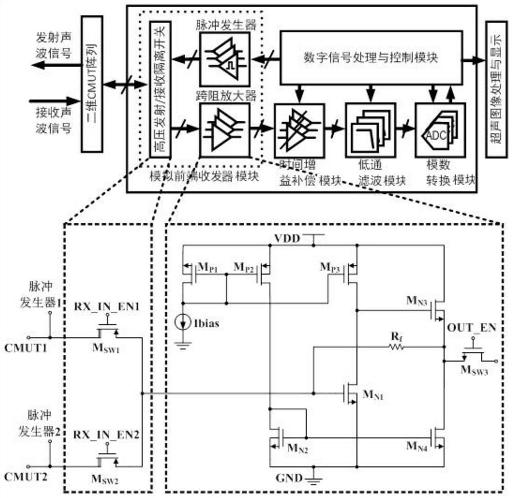
[0024] figure 1 It is a structural schematic diagram of the three-dimensional ultrasonic imaging system of the present invention, such as figure 1 As shown, the system includes: a two-dimensional CMUT array module, an analog front-end transceiver module, a time gain compensation module, a low-pass filter module, an ADC module, a digital signal processing and control module, and an ultrasonic image processing and display module. Among them, the two-dimensional CMUT array...


PUM

PropertyMeasurementUnit
electrical resistanceaaaaaaaaaa

Abstract

The invention provides a three-dimensional ultrasonic imaging system, including: a two-dimensional CMUT array, an analog front-end transceiver module, a time gain compensation module, a low-pass filter module, an ADC conversion module, a digital signal processing and control module, and the analog front-end transceiver module The device includes: a high-voltage transmitting / receiving isolation switch, a transimpedance amplifier, and a pulse generator; the two-dimensional CMUT array and the array of analog front-end transceiver modules are correspondingly connected through vertical silicon vias; the transimpedance amplifier includes: a single-ended amplifier and a feedback resistor R f ; The single-ended amplifier is composed of a common-source amplifier MN1 cascaded with an N-type source follower MN3. The three-dimensional ultrasonic imaging system provided by the present invention has the characteristics of low input resistance, high transconductance and feedback resistance of the high-frequency transimpedance amplifier in the analog receiver, so that the system has a wider frequency bandwidth and enables the system to work at higher frequencies , the spatial resolution of 3D imaging is higher.

Description

technical field [0001] The invention relates to the field of ultrasonic medical imaging, in particular to a three-dimensional ultrasonic imaging system. Background technique [0002] With the development of electronic technology and ultrasonic theory, ultrasonic imaging testing equipment has been widely used in various industries, such as medical imaging diagnosis, seabed landform mapping, resource survey, industrial nondestructive testing, ultrasonic ranging, underwater shipwreck salvage, ship identification, etc. Numerous areas. Ultrasonic imaging refers to the use of ultrasonic beams to detect target objects, and after processing steps such as detection and storage of received echo or transmitted wave signals, information such as target distance, outline and internal structure are obtained according to different imaging methods, and finally Display the above information in the form of images. At present, the commonly used scanning ultrasonic imaging methods mainly inclu...

Claims


Application Information

Patent Timeline
Patent Type & Authority Patents(China)
IPC IPC(8): G01N29/22G01D11/00
CPCG01D11/00G01N29/22
Inventor 黄汐威
Owner 成都华芯微医疗科技有限公司
Why Eureka
Try Eureka