An automatic chip removal device for cutting equipment

A cutting equipment, automatic cleaning technology, applied in the direction of metal processing equipment, manufacturing tools, metal processing machinery parts, etc., can solve the problems of insufficient automaticity and inconvenient cleaning, and achieve the effects of cost saving, prolonging service life and good wear resistance

Inactive Publication Date: 2020-07-24
UNIV FOR SCI & TECH ZHENGZHOU
View PDF8 Cites 0 Cited by
  • Summary
  • Abstract
  • Description
  • Claims
  • Application Information

AI Technical Summary

Problems solved by technology

[0005] Aiming at the deficiencies of the prior art, the present invention provides an automatic chip cleaning device for cutting equipment, which has the advantage of automatically cleaning the chips generated by cutting, and solves the problem that the current cleaning device is not automatic enough when cleaning chips, thus Inconvenient problem when cleaning

Method used


Image

  • An automatic chip removal device for cutting equipment
  • An automatic chip removal device for cutting equipment
  • An automatic chip removal device for cutting equipment

Examples


Embodiment 1

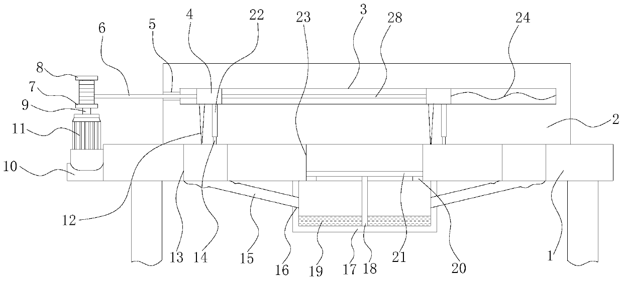
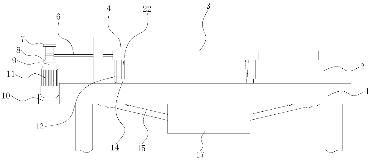
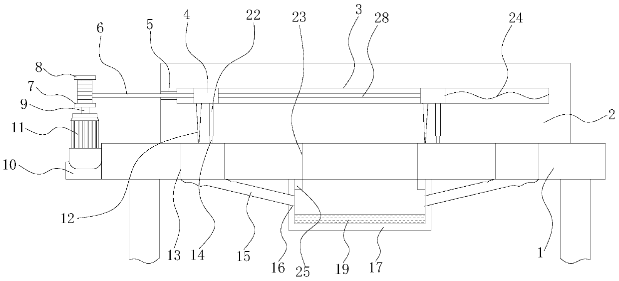
[0038] Such as Figure 1-2As shown, an automatic chip removal device for cutting equipment includes a cutting table 1, and a chip removal hole 13 penetrating the cutting table 1 is opened on the cutting table 1, and auxiliary holes 23 are symmetrically opened on both sides of the chip removal hole 13; the cutting table The upper surface of 1 is fixed with a backplane 2, and the front of the backplane 2 is provided with a moving groove 3 along the length direction of the backplane 2, and two sliding rods 4 are slidably connected in the moving groove 3, and the two sliding rods 4 extend out of the moving groove 3. The lower surface of the back is connected with a scraper 12 and a vertical plate 22 arranged side by side. The two side walls of the scraper 12 are inclined from top to bottom to the center of the scraper 12 to form two symmetrical cleaning surfaces. There are anti-scratch pieces; the bottom of the riser 22 is bonded with bristles 14; the two slide bars 4 are connecte...

Embodiment 2

[0047] A preparation method of a scraper, the preparation method of the scraper mainly includes the following steps:

[0048] Step 1: Mix butyl rubber, calcium oxide, stearic acid, clay, coal tar pitch, silicon dioxide, glass fiber, iron oxide and aluminum oxide in the following parts by weight: 60-100 parts of butyl rubber, calcium oxide 2 to 7 parts, 1 to 3 parts of stearic acid, 4 to 8 parts of clay, 8 to 18 parts of coal tar pitch, 3 to 7 parts of silicon dioxide, 2 to 3 parts of iron oxide and 5 to 13 parts of aluminum oxide;

[0049] Step 2: Put the mixed raw material obtained in Step 1 into a smelting furnace for smelting. The smelting temperature of the smelting furnace is 130-180° C.; the smelting is carried out in two stages, and the first stage is carried out at 130-160° C. For the first smelting, the smelting time is 10-15 minutes. After the first smelting is completed, cool to room temperature and then perform the second smelting. The second smelting is smelting a...

Embodiment 3

[0055] A preparation method of a scraper, the preparation method of the scraper mainly includes the following steps:

[0056] Step 1: Mix butyl rubber, calcium oxide, stearic acid, clay, coal tar pitch, silicon dioxide, glass fiber, iron oxide and aluminum oxide in the following parts by weight: 60 parts of butyl rubber, 2 parts of calcium oxide , 1 part of stearic acid, 4 parts of clay, 8 parts of coal tar pitch, 3 parts of silicon dioxide, 2 parts of iron oxide and 5 parts of aluminum oxide;

[0057] Step 2: Put the mixed raw material obtained in Step 1 into the melting furnace for smelting. The smelting is carried out in two stages. In the first stage, the first smelting is carried out under the condition of 130°C. The smelting time is 10 minutes, and the first smelting is completed. After cooling to room temperature, the second smelting is carried out, and the second smelting is smelted at 160°C for 35 minutes; after the second smelting is completed, the temperature is kep...


PUM

PropertyMeasurementUnit
lengthaaaaaaaaaa
lengthaaaaaaaaaa

Abstract

The invention relates to the technical field of cutting equipment, and discloses an automatic chip removing device of the cutting equipment. The automatic chip removing device comprises a cutting table. An auxiliary hole and chip discharge holes symmetric about the auxiliary hole are formed in the cutting table. A back plate is fixed to the cutting table, a movable groove is formed in the back plate, two sliding rods are arranged in the movable groove, the lower surfaces of the two sliding rods are connected with scraper blades and vertical plates, two cleaning surfaces are formed on the two side walls of the scraper blades, and anti-scratching pieces are arranged on the cleaning surfaces. Bristles are arranged at the bottoms of the vertical plates, a telescopic spring is connected betweenthe side wall of one sliding rod and the end of the movable groove, and the side wall of the other sliding rod is connected with a rope driven by a drive assembly. The scraper blades are mainly prepared through the six steps of raw material mixing, smelting, adding of glass fibers, extrusion forming, ceramic sand blasting and bonding of the anti-scratching pieces. Chips in the cutting equipment are convenient to remove; and meanwhile, the abrasion resistance of the scraper blades in the chip removing process is good, no frictional losses are caused to the cutting table, and the scraper bladescannot be damaged in the chip removing process.

Description

technical field [0001] The invention relates to the technical field of cutting equipment, in particular to an automatic chip cleaning device for cutting equipment. Background technique [0002] Cutting equipment processing is the use of the relative movement of cutting tools and workpieces to remove excess metal layers from blanks (castings, forgings, profiles, etc.) to obtain machine parts with dimensional accuracy, shape and position accuracy, and surface quality that fully meet the requirements of the drawing method. Most of the parts processed by casting, forging and welding are blanks of parts, which are rarely used directly on the machine, and further cutting processing is required to meet the technical requirements of the parts. When the cutting equipment is working, a lot of damage will be generated due to cutting. Debris, and a cleaning device is needed when the debris is cleaned, but the current cleaning device is not automatic enough when cleaning the debris, so ...

Claims


Application Information

Patent Timeline
Patent Type & Authority Patents(China)
IPC IPC(8): B23Q11/00C08L23/22C08L95/00C08K13/04C08K7/14C08K3/22C08K5/09C08K3/36
CPCB23Q11/0042C08K2003/2206C08K2003/2227C08K2003/2265C08K2201/004C08L23/22C08L95/00C08K13/04C08K7/14C08K3/22C08K5/09C08K3/36
Inventor 赵纪国刘世平张亚林余涛刘永辉
Owner UNIV FOR SCI & TECH ZHENGZHOU
Why Eureka
Try Eureka