Composite modification method for surface protection of neodymium iron boron magnet

A compound modification and surface modification technology, which is applied in the fields of permanent magnet manufacturing, inductor/transformer/magnet manufacturing, ion implantation plating, etc., can solve the problems of insufficient improvement of the surface corrosion resistance of NdFeB magnets, etc.

Active Publication Date: 2019-08-06
INST OF MECHANICS - CHINESE ACAD OF SCI
View PDF6 Cites 5 Cited by
  • Summary
  • Abstract
  • Description
  • Claims
  • Application Information

AI Technical Summary

Problems solved by technology

[0006] To this end, the embodiment of the present invention provides a composite modification method for surface protection of NdFeB magnets, which combines conventional magnetron sputtering coating technology, high-power pulse magnetron sputterin...

Method used


Image

  • Composite modification method for surface protection of neodymium iron boron magnet

Examples


Embodiment 1

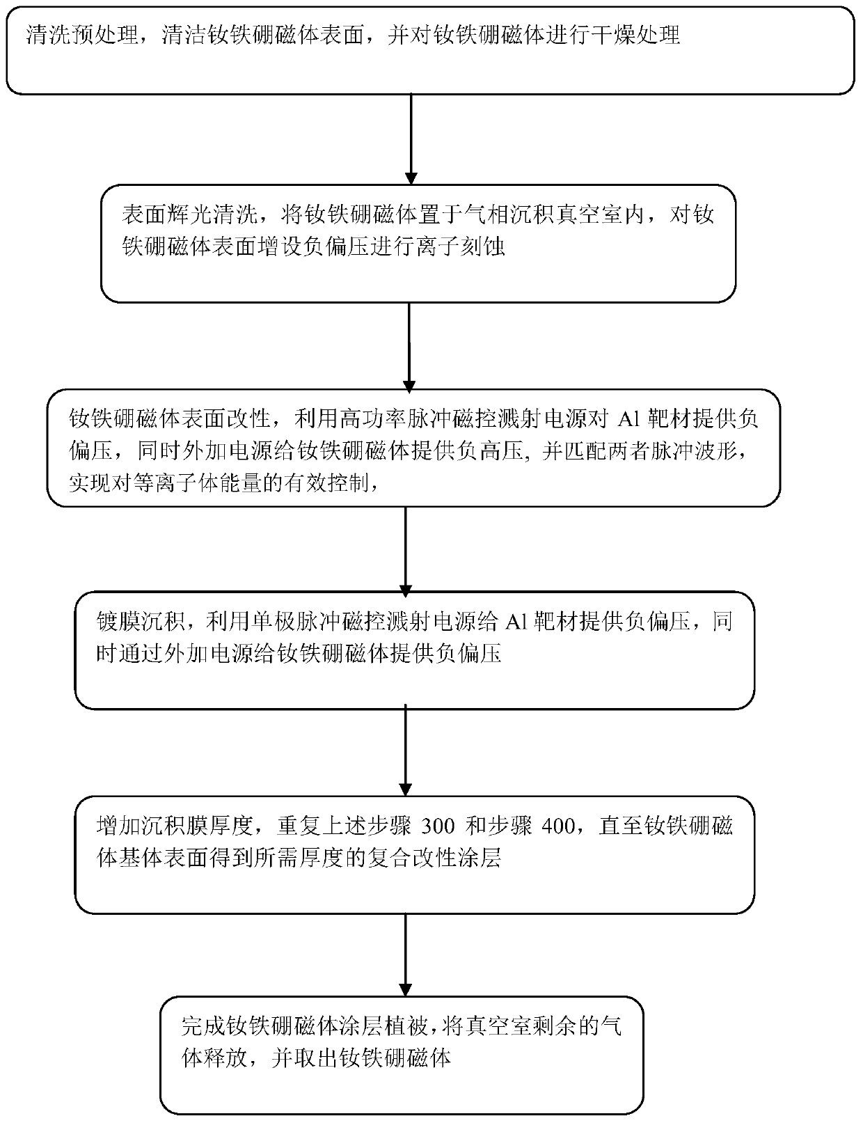
[0045] Such as figure 1 As shown, the present invention provides a composite modification method for surface protection of NdFeB magnets. The method includes three technologies: conventional magnetron sputtering, high-power pulse magnetron sputtering and plasma immersion ion implantation deposition. Among them, the conventional magnetron sputtering technology is used to ensure the overall deposition rate of the coating; the high-power pulse magnetron sputtering technology is used to generate high-density Al plasma, and at the same time, the substrate is loaded with pulsed high voltage to realize the plasma immersion of Al ions Inject the deposition process.

[0046] Including the following steps:

[0047] Step 100, cleaning pretreatment, cleaning the surface of the NdFeB magnet, and drying the NdFeB magnet.

[0048] Pretreatment includes surface oxide layer treatment, degreasing treatment, derusting treatment and dirt treatment of the magnet. Firstly, the NdFeB magnet is mec...

Embodiment 2

[0076] The present invention will be described in further detail below in conjunction with the accompanying drawings and actual cases. Taking the deposition of Al coating on the surface of NdFeB magnets as an example, select NdFeB magnets with a size of 25mm*25mm*12mm, and the specific steps are as follows:

[0077] Step 1: Pre-treatment of NdFeB magnet coating: Mechanically polish the NdFeB magnet, place it in acetone and alcohol for ultrasonic cleaning, and then use an air pump to dry the magnet surface.

[0078] Step 2: Place the NdFeB magnet on the workpiece rack in the vacuum chamber, and use a mechanical pump and a molecular pump to evacuate the chamber so that the chamber reaches a high vacuum level, and the vacuum degree is less than or equal to 10-3Pa.

[0079] Step 3: The argon gas flowing into the vacuum chamber is controlled by a mass flow meter, and the gas in the vacuum chamber is 1.5 Pa.

[0080] Step 4: Provide a negative pulse voltage to the workpiece holder ...


PUM


Abstract

The embodiment of the invention discloses a composite modification method for surface protection of a neodymium iron boron magnet, which comprises the steps of carrying out pretreatment on the neodymium iron boron magnet; placing the magnet in a workpiece rest of a vacuum chamber, and extracting the air of the vacuum chamber; providing negative bias voltage to the workpiece rest through an external power supply, and completing glow cleaning for the magnet; providing negative bias voltage to an Al target material through a high-power pulse magnetron sputtering power supply to generate high-density Al plasmas, providing negative high voltage to the workpiece rest through the external power supply, and matching the pulse waveforms to complete the Al plasma immersion ion implantation and deposition process of the workpiece; providing negative bias voltage to the Al target material through a single-pole pulse magnetron sputtering power supply, and providing negative bias voltage to the workpiece rest through the external power supply so as to deposit an Al film on the surface of the workpiece; and repeating the processes of magnetron sputtering and plasma immersion ion implantation anddeposition to obtain a composite modified coating on the substrate surface of the workpiece, so that the corrosion resistance of the surface of the neodymium iron boron magnet is improved.

Description

technical field [0001] The embodiment of the present invention relates to the technical field of low-temperature plasma surface modification, in particular to a compound modification method for surface protection of NdFeB magnets. Background technique [0002] NdFeB (NdFeB), as the third generation rare earth permanent magnet material, has excellent magnetic properties and high cost performance. At present, China's NdFeB industry has accounted for nearly 80% of the global market share, and it is the world's largest sintered NdFeB magnet industry. center. Because of its high efficiency and energy saving, light weight, small size, and good control and speed regulation, NdFeB magnets are widely used in sunrise industries such as wind power generation, new energy vehicles, and energy-saving home appliances. However, the poor corrosion resistance of NdFeB magnets seriously hinders its large-scale application in the industrial field. Therefore, improving the corrosion resistance...

Claims


Application Information

Patent Timeline
IPC IPC(8): H01F41/02C23C14/35C23C14/48C23C14/34C23C14/16C23C14/02
CPCC23C14/022C23C14/165C23C14/3485C23C14/35C23C14/48H01F41/026
Inventor 夏原许亿李光
Owner INST OF MECHANICS - CHINESE ACAD OF SCI
Why Eureka
Try Eureka