Method for shortening pulse and obtaining adjustable picosecond pulse
A second pulse and pulse technology, which is applied in the field of shortening pulses and obtaining adjustable picosecond pulses, can solve the problems of complex structure and high cost, and achieve the effect of small size, low cost and good application prospects
- Summary
- Abstract
- Description
- Claims
- Application Information
AI Technical Summary
Problems solved by technology
Method used
Image
Examples
Embodiment 1
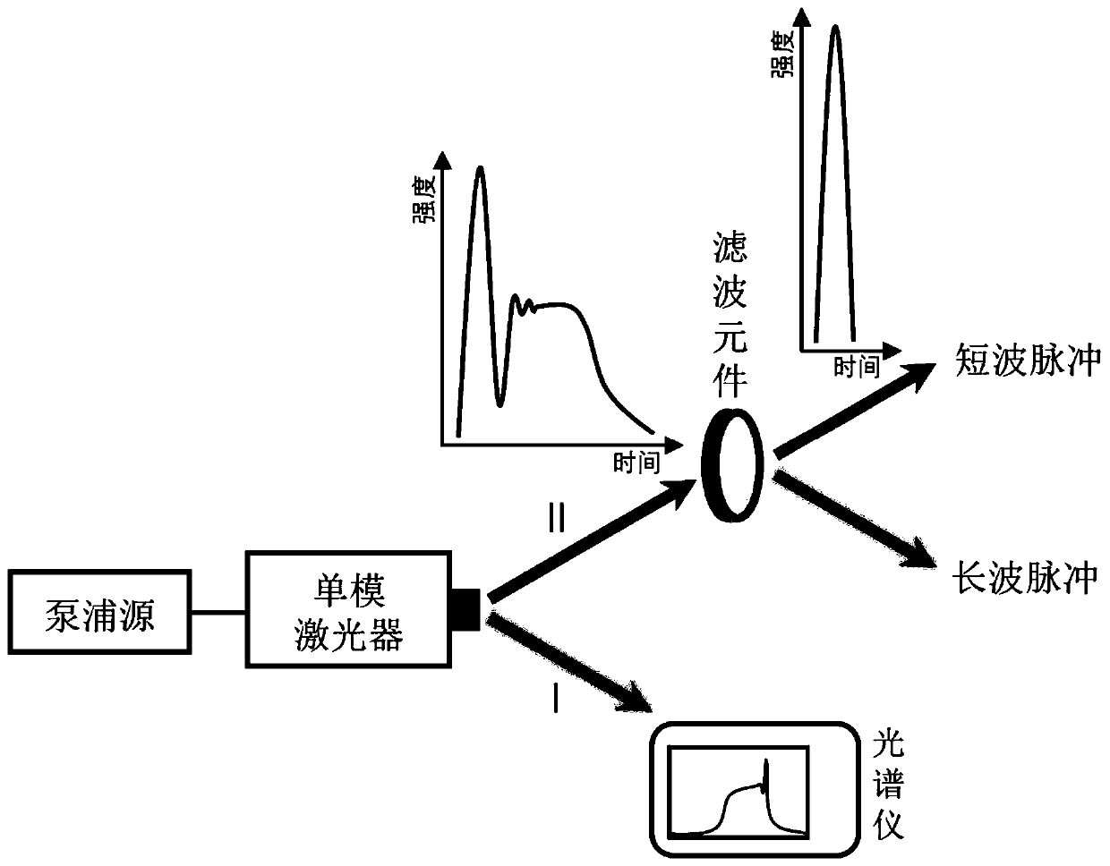
[0022] Such as figure 1 Shown is a structural schematic diagram of a specific embodiment of the present invention.
[0023] The pumping source in this embodiment is an electric pulse generator with adjustable pulse width, pulse amplitude and repetition frequency.
[0024] The laser in this embodiment is a 980nm GaAs-based single-mode gain switch DBR-LD capable of high-speed modulation.
[0025] The filter element in this embodiment is a narrow channel bandpass filter.
[0026] First, modulate the electrical pulse generator to generate a square wave electrical pulse of 0.6 nanoseconds and 5 volts, and then pump the laser to generate pulsed laser light with chirped pulse components and steady-state pulse components. The wavelength range is 976.5 nm to 980.3 nm. Select a filter with a center wavelength of 978 nm and a bandwidth of 1 nm, and obtain short-wave laser light after the laser is filtered by the filter of the II optical path.
[0027] The half-maximum width (FWHM) of...
Embodiment 2
[0029] Such as figure 2 Shown is a structural schematic diagram of a specific embodiment of the present invention.
[0030] The pumping source in this embodiment is an electric pulse generator with adjustable pulse width, pulse amplitude and repetition frequency.
[0031] The laser in this embodiment is a 1550nm InGaAsP multi-quantum well single-mode gain switch DFB-LD capable of high-speed modulation.
[0032] The fiber waveguide in this embodiment is a single-mode fiber.
[0033] The filter in this embodiment is an adjustable narrowband bandpass filter with a bandwidth of 1 nanometer.
[0034] In this embodiment, an erbium-doped fiber amplifier EDFA is used to amplify and filter the optical pulses, thereby compensating for the previous loss of light intensity.
[0035] First, the electric pulse generator is modulated to generate a 3.1 volt square wave electric pulse with a duration of 0.6 nanoseconds. After the pump laser is pumped, a pulsed laser with a chirped pulse co...
Embodiment 3
[0038] The pumping source in this embodiment is an electric pulse generator with adjustable pulse width, pulse amplitude and repetition frequency.
[0039] The laser in this embodiment is a 1310nm InGaAsP multi-quantum well single-mode gain switch VCSEL capable of high-speed modulation.
[0040] In this embodiment, a semiconductor optical amplifier (SOA) is used to amplify the pulse laser before filtering to ensure the output laser power.
[0041] The fiber waveguide in this embodiment is a single-mode fiber.
[0042] The filter in this embodiment is an adjustable narrow band pass filter with a bandwidth of 1 nanometer.
[0043] First, the modulated electrical pulse generator generates a 4-volt square-wave electrical pulse with a duration of 0.6 nanoseconds, and excites a gain-switched semiconductor laser. The laser generates pulsed laser light with chirped pulse components and steady-state pulse components, and the filtered wavelength range measured by the spectrometer is 1...
PUM
 Abstract
Description
Claims
Application Information
 - R&D
- Intellectual Property
- Life Sciences
- Materials
- Tech Scout
- Unparalleled Data Quality
- Higher Quality Content
- 60% Fewer Hallucinations
Browse by: Latest US Patents, China's latest patents, Technical Efficacy Thesaurus, Application Domain, Technology Topic, Popular Technical Reports.
© 2025 PatSnap. All rights reserved.Legal|Privacy policy|Modern Slavery Act Transparency Statement|Sitemap|About US| Contact US: help@patsnap.com


