
Composite electrolyte membrane and preparation method and application thereof

A composite electrolyte membrane and electrolyte technology, which is applied in the field of solid electrolytes, can solve the problems of reducing the mechanical strength and energy density of electrolytes, the inability to ensure complete filling of electrolyte materials, and reducing the movement capacity of molecular chains, so as to reduce the risk of thermal runaway and ensure mechanical strength. and ionic conductivity, and the effect of improving the safety performance of thermal abuse

Inactive Publication Date: 2019-11-15
KUNSHAN BAOTRON NEW ENERGY TECH CO LTD
View PDF7 Cites 15 Cited by
  • Summary
  • Abstract
  • Description
  • Claims
  • Application Information

AI Technical Summary

Problems solved by technology

However, the method of introducing carbonate-based solid electrolytes is generally copolymerization or mixing. The copolymerization method is easy to change the flexibility of the molecular chain, reducing the mobility of the molecular chain and thus weakening the ion conductivity, while the mixing method has compatibility problems and is easy to reduce the mechanical strength of the electrolyte. and energy density
Based on this, a large number of experimental studies have been carried out in the industry by coating the surface of the porous membrane carrier with an electrolyte gel layer. This kind of electrolyte membrane with the help of a porous carrier can improve the strength and flexibility of the electrolyte membrane, but due to the porous carrier The thickness of the electrolyte is generally relatively thick, and the pores are mostly non-through holes with large pore diameters. If the control is not good, it will easily lead to micro-short circuit. The surface coating technology cannot ensure that the electrolyte material is completely filled. In the actual application process, there will be a hollow phenomenon, resulting in ion conduction. Impossible, battery impedance increases, unable to work normally

Method used


Image

  • Composite electrolyte membrane and preparation method and application thereof
  • Composite electrolyte membrane and preparation method and application thereof

Examples


preparation example Construction

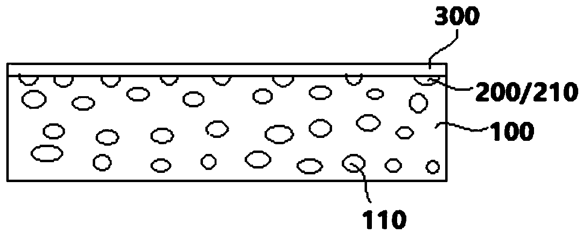
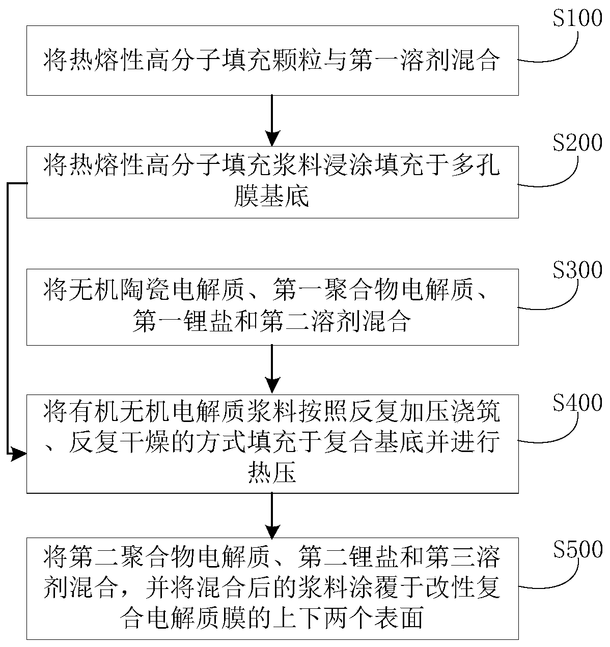
[0058] According to the method for preparing a composite electrolyte membrane according to an embodiment of the present invention, the porous membrane substrate is filled with hot-melt polymer filler particles, which is conducive to reducing the pore size and porosity of the porous membrane substrate, and at the same time, when the heating temperature of the composite electrolyte membrane reaches the thermal melting point At the melting point of the polymer filler particles, the hot-melt polymer filler particles melt and penetrate into the surface of the adjacent organic-inorganic electrolyte particles. Because the hot-melt polymer filler particles have insulating properties, the effect of cutting off the conductive path is achieved. Reduce the risk of thermal runaway and improve the safety performance of battery thermal abuse; further, the organic-inorganic electrolyte filling layer can make the composite electrolyte membrane have high density, which can effectively ensure the ...

Embodiment 1

[0063] Mix hot-melt polymer filled particles modified ethylene-vinyl acetate copolymer with a melting point of 125°C and an average particle size of 0.5 μm, binder SBR and deionized water as the first solvent to obtain a solid content of 20 wt%. Hot-melt polymer filling slurry with a viscosity of 400mPa.s;

[0064] The hot-melt polymer filling slurry is dip-coated and filled in the electrospinning polyimide porous membrane substrate with a thickness of 15 μm, a porosity of 90%, and an average pore diameter of 10 μm, and then dried to obtain a composite substrate. The coating time is 2 minutes, and the drying temperature is 80°C;

[0065] The inorganic ceramic electrolyte LAGP ceramic oxide and the first polymer electrolyte modified PEO-based organic polymer, the first lithium salt LiCLO 4 mixed with a second solvent, acetonitrile, so as to obtain an organic-inorganic electrolyte slurry. Wherein, the mass ratio of the inorganic ceramic electrolyte to the first polymer electro...

Embodiment 2

[0069] Mix hot-melt polymer filled particle-modified polyethylene with a melting point of 130°C and an average particle size of 0.8 μm, binder LA133, and the first solvent deionized water to obtain a solid content of 15 wt % and a viscosity of 800 mPa. s hot-melt polymer filling paste;

[0070] Dip-coat the hot-melt polymer filling slurry into the porous film substrate PET non-woven fabric with a thickness of 20 μm, a porosity of 80%, and an average pore diameter of 6 μm, and obtain a composite substrate after drying. Among them, the dip-coating time 1min, drying temperature is 70°C;

[0071]The inorganic ceramic electrolyte LATP ceramic oxide, the first polymer electrolyte modified PPC-based organic polymer electrolyte, the first lithium salt LiTFSI, and the second solvent acetonitrile were mixed so as to obtain an organic-inorganic electrolyte slurry. Wherein, the mass ratio of the inorganic ceramic electrolyte to the first polymer electrolyte and the first lithium salt is ...


PUM

PropertyMeasurementUnit
Thicknessaaaaaaaaaa
Average pore sizeaaaaaaaaaa
Thicknessaaaaaaaaaa

Abstract

The invention discloses a composite electrolyte membrane and a preparation method and application thereof. The composite electrolyte membrane comprises a porous membrane substrate which is filled withhot-melt polymer filling particles, an organic-inorganic electrolyte filling layer which is arranged on at least part of the surface of the porous membrane substrate and comprises organic-inorganic electrolyte of which at least part fills the porous membrane substrate, and a polymer electrolyte buffer layer which is arranged on at least part of the organic-inorganic electrolyte filling layer andcovers the porous membrane substrate as a surface in contact with electrodes. The composite electrolyte membrane has the advantages of high safety performance, excellent mechanical strength, high conductivity at room temperature and good interface compatibility with positive and negative electrodes.

Description

technical field [0001] The invention belongs to the technical field of solid electrolytes, in particular, the invention relates to a composite electrolyte membrane and its preparation method and application. Background technique [0002] All-solid polymer electrolytes and fast ion conductor composite electrolytes can effectively solve the shortcomings of traditional liquid electrolytes and improve the safety performance of lithium-ion batteries. High ionic conductivity, good compatibility with electrodes, excellent mechanical properties, and wide electrochemical window are the characteristics that an ideal solid-state polymer electrolyte should have, but currently commonly used all-solid-state polymer electrolytes are difficult It has the above characteristics at the same time. For example, the traditional PEO system lithium-ion battery solid electrolyte has insufficient room temperature ionic conductivity and mechanical strength. One method to improve the room temperature ...

Claims


Application Information

Patent Timeline
IPC IPC(8): H01M10/0565H01M10/0562H01M10/058H01M10/0525
CPCH01M10/0525H01M10/0562H01M10/0565H01M10/058H01M2200/10H01M2300/0091H01M2300/0094Y02E60/10Y02P70/50
Inventor 张国军邱昭政赵育松梁世硕
Owner KUNSHAN BAOTRON NEW ENERGY TECH CO LTD
Learn More