Method for reducing carbon dioxide into porous carbon material, and porous carbon material and application thereof

A porous carbon material, carbon dioxide technology, applied in the direction of nano-carbon, carbon preparation/purification, graphene, etc., to achieve high electrical conductivity, good crystallization performance, and high specific surface area

Active Publication Date: 2020-02-21
SOUTH CHINA NORMAL UNIVERSITY
View PDF7 Cites 6 Cited by
  • Summary
  • Abstract
  • Description
  • Claims
  • Application Information

AI Technical Summary

Problems solved by technology

However, few studies have focused on the reduction of CO2 to functional carbonaceous materials

Method used


Image

  • Method for reducing carbon dioxide into porous carbon material, and porous carbon material and application thereof
  • Method for reducing carbon dioxide into porous carbon material, and porous carbon material and application thereof
  • Method for reducing carbon dioxide into porous carbon material, and porous carbon material and application thereof

Examples


Embodiment 1

[0038] Preparation of dense porous carbon materials: Taking pure magnesium as an example, 15 g of Mg powder was placed in Al 2 o 3 vessel, in gentle CO 2 Under air flow (flow rate: 60 Sccm), heat in a tube furnace at 680° C. for 6 h. After the reaction, the black product was collected and stirred in 2.0M HCl solution for 10 h at room temperature to remove MgO. The mixture was then filtered and rinsed several times with deionized water until the pH of the filtrate reached around neutral. Finally, the separated solid carbon product was rinsed with ethanol and dried overnight at room temperature. The resulting product is called C-Ms.

Embodiment 2

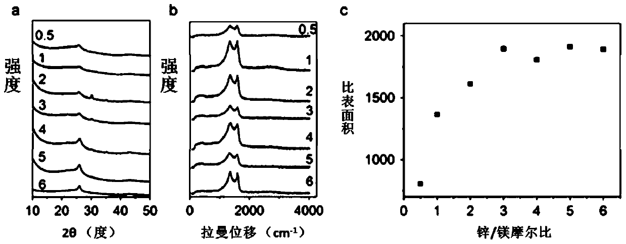
[0040] Change pure magnesium into the mixture of magnesium and zinc, repeat the operation process of embodiment 1, the product obtained is called C-MZ-n, when the Zn / Mg ratio is greater than or equal to 3, the product is called C-MZ-3, measure The analysis results are as follows:

[0041] Compared with C-Ms, the specific surface area of ​​C-MZ-n is indeed significantly increased, when the Zn / Mg ratio is greater than or equal to 3, it is 1900m 2 ( figure 1 c). When pure Zn is used as reducing agent for CO 2 During the reduction of Zn, although Zn was oxidized to ZnO, no carbon black was formed after the simple visual reaction. Furthermore, compared with C-Ms, the graphitic crystal features of all C-MZ-n are obviously weakened, which can be seen from the lower resolution XRD peaks and higher ID / IG ratio in Raman spectra ( figure 1 a, figure 1 b).

[0042] The nanoporosity of C-MZ-n, C-MZ-3 was observed by transmission electron microscopy (TEM). C-MZ-3 consists of densely ...

Embodiment 3

[0046] Replace pure magnesium with a mixture of magnesium and copper, and use a mixture of Mg and Cu powders with an equal ratio of substances, at 60SCCMCO 2 Heating at 680°C for 12h under airflow. After the product is cooled, stir it with 2mol / L HCl solution for 12 hours to remove MgO, remove Cu with concentrated ammonia water and oxygen, then filter and wash the mixture several times with deionized water and ethanol, and finally, dry the product at 80 degrees Celsius overnight . The resulting carbon product C-Mg / Cu. As a comparison, the carbon product using Mg alone is called C-Ms, and the measurement and analysis results are as follows:

[0047] By comparing the XRD patterns of C-Mg and C-Mg / Cu, it can be seen that the addition of copper greatly improves the crystallinity of the material. Electron microscopy (HRTEM) images confirmed the highly graphitized structure of C-Mg / Cu, where graphene layers are ordered stacked tens of nanometers in C-Mg / Cu and less than 20 nm in ...


PUM

PropertyMeasurementUnit
densityaaaaaaaaaa
electrical conductivityaaaaaaaaaa

Abstract

The invention belongs to the technical fields of metal thermal reduction reactions and graphene materials, and particularly discloses a method for reducing carbon dioxide into a porous carbon material, and the porous carbon material and application thereof. The method comprises the following specific steps: carrying out heat treatment on magnesium-containing metal in a CO2-containing atmosphere; after a reaction is finished, stirring an obtained product in an HCl solution; and purifying the obtained mixture, and carrying out drying overnight at room temperature to obtain the porous carbon material. The specific surface area of the porous carbon material prepared from the magnesium-zinc mixture can reach 1800-2000 m<2>/g; the conductivity of the material is as high as 1000 to 1100 S/m; thecapacitance retention rate is high; the tap density of the material is almost the same as the tap density of activated carbon and is 0.60-0.65 g/cm<3>; so the porous carbon material is an ideal material for preparing a high-power electrochemical capacitor electrode. The porous carbon material prepared from the magnesium-copper mixture has the advantages of favorable specific surface area and goodcrystallinity, and is an ideal material for preparing electrodes of microbial fuel cells.

Description

technical field [0001] The invention belongs to the technical field of metallothermal reduction reaction and graphene materials, and in particular relates to a method for reducing carbon dioxide into porous carbon materials, porous carbon materials and applications. Background technique [0002] Combustion of fossil fuels remains the main source of energy for electricity generation worldwide. This process produces a large amount of carbon dioxide, which is considered to be a major factor in global climate change, and it is necessary to use the abundant and wasted carbon dioxide as a feedstock gas to synthesize valuable chemicals. Photocatalysis and hydrogenation have been shown to efficiently convert carbon dioxide into small organic molecules, such as formic acid and methanol, among others. However, few studies have focused on the reduction of CO2 to functional carbonaceous materials. Contents of the invention [0003] In order to overcome the above-mentioned shortcomin...

Claims


Application Information

Patent Timeline
Patent Type & Authority Applications(China)
IPC IPC(8): C01B32/05C01B32/184H01M4/96
CPCC01B32/05C01B32/184H01M4/96Y02E60/50
Inventor 邢震宇马雁龙冯翔龙李爱菊钟华霞
Owner SOUTH CHINA NORMAL UNIVERSITY
Why Eureka
Try Eureka