Ion source, ion injection device and ion source operation method

An ion source and ion technology, applied in the field of ion sources, can solve problems such as poor production efficiency, lower yield, vacuum pump failure, etc., and achieve the effect of changing maintenance cycle, decreasing resistance value, and long maintenance cycle

Active Publication Date: 2020-04-10
ULVAC INC
View PDF5 Cites 0 Cited by
  • Summary
  • Abstract
  • Description
  • Claims
  • Application Information

AI Technical Summary

Problems solved by technology

[0009] However, in such a way of making aluminum nitride etc. with PF 3 In the reaction method, insulating aluminum fluoride (AlF x ), there is a problem that the generated aluminum fluoride causes abnormal discharge in the vacuum chamber 51 via the insulating film (especially the insulating film 160 among the insulating films 160 and 161 ) attached to the inner wall of the vacuum chamber 51
[0010] If such an abnormal discharge occurs, in addition to fluctuations in the ion beam current and a decrease in the yield of the ion implantation target object, electromagnetic noise may cause failure of the power supply of the ion implantation device and the vacuum pump.
[0011] Therefore, conventionally, when abnormal discharges frequently occur, the vacuum chamber 51 of the ion source 50 is opened to the atmosphere to remove the insulating film 160. However, in the prior art, such maintenance must be performed frequently, which may degrade production efficiency. topic

Method used


Image

  • Ion source, ion injection device and ion source operation method
  • Ion source, ion injection device and ion source operation method
  • Ion source, ion injection device and ion source operation method

Examples


Embodiment Construction

[0045] Hereinafter, embodiments of the present invention will be described with reference to the drawings.

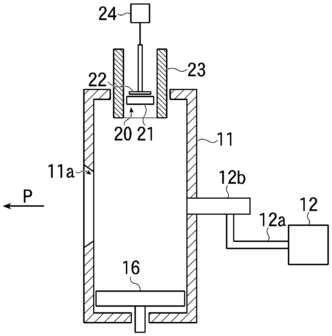
[0046] figure 1 It is a schematic configuration diagram showing the whole of an ion implantation apparatus using the ion source of the present invention.

[0047] Such as figure 1 As shown, ion source 10 , traveling chamber 2 , mass spectrometer 3 , accelerator 4 , scanning device 5 , and implantation chamber 6 described later are sequentially connected to constitute ion implantation apparatus 1 of this example.

[0048] Furthermore, this ion implantation apparatus 1 is configured such that the ion source 10 , the traveling chamber 2 , the acceleration device 4 , and the implantation chamber 6 are evacuated by vacuum evacuation devices 9 a to 9 d , respectively.

[0049] A gas supply unit 12 described later is connected to the ion source 10 , the gas supplied by the gas supply unit 12 is ionized, and the generated ions are made to travel inside the traveling chamber...


PUM


Abstract

The present invention provides a technique for suppressing an abnormal electric discharge inside an ion generation container from an ion source, which is caused by an insulation film originating fromby-products when an ionization gas and an ion source material are reacted to generate ions. This ion source comprises: a vacuum chamber (10A) having a cooling mechanism; an ion generation container (11) provided inside the vacuum chamber (10A), wherein the ionization gas and the ion source material are reacted to generate the ions; an extraction electrode (15) provided inside the vacuum chamber (10A), for extracting the ions generated inside the ion generation container (11) to generate an ion beam; and a shielding member (30) provided on the inner side and in the vicinity of an inner wall (10d) of the vacuum chamber (10A), having a main body section (31) comprising an electric conductive metal for the purpose of blocking the adhesion of an insulating material onto the inner wall (10d) ofthe vacuum chamber (10A). Provided in the main body section (31) of the shielding member (30) are a plurality of protrusion-shaped support parts (32), which establish contact with the inner wall (10d)of the vacuum chamber (10A) to support the main body section (31) in such a manner that the mounting thereof onto the inner wall (10d) of the vacuum chamber (10A) establishes a gap therebetween.

Description

technical field [0001] The present invention relates to ion sources, in particular to the maintenance technology of ion sources used in ion implantation devices. Background technique [0002] In recent years, methods for manufacturing silicon carbide (SiC) substrates that are superior in heat resistance and voltage resistance compared with conventional silicon (Si) substrates have been established, and they can be obtained relatively cheaply. [0003] Among the processes using the SiC substrate, there is a process of implanting aluminum ions as a dopant, and an ion implantation apparatus having an ion source for generating an aluminum ion beam is used. [0004] Figure 10 It is a sectional view showing the inside of a conventional ion source. [0005] Such as Figure 10 As shown, the ion source 50 has a vacuum tank 51 formed of a metal such as stainless steel in a cylindrical shape and connected to a vacuum exhaust device (not shown). The ion generating container 52 that r...

Claims


Application Information

Patent Timeline
Patent Type & Authority Applications(China)
IPC IPC(8): H01J27/04H01J37/08
CPCH01J37/08H01J37/3171H01J2237/022H01J2237/0213H01J2237/0268H01J27/08H01J27/04C23C14/48H01J37/16H01J2237/002
Inventor 东明男佐佐木德康寺泽寿浩
Owner ULVAC INC
Why Eureka
Try Eureka