Circularly polarized light detector and preparation method thereof

A circularly polarized light and device technology, applied in the field of photodetection devices, can solve the problems of being unable to apply small integrated optical systems, etc., and achieve the effect of ultra-thin thickness and broad application prospects

Active Publication Date: 2020-04-17
PEKING UNIV
View PDF1 Cites 20 Cited by
  • Summary
  • Abstract
  • Description
  • Claims
  • Application Information

AI Technical Summary

Problems solved by technology

With the miniaturization and integration of optical systems, the traditional method of detecting circularly polarized

Method used


Image

  • Circularly polarized light detector and preparation method thereof
  • Circularly polarized light detector and preparation method thereof
  • Circularly polarized light detector and preparation method thereof

Examples


preparation example Construction

[0052] The preparation method of the circularly polarized light detection device based on monolayer molybdenum diselenide and chiral surface plasmon metasurface is further given below, and the preparation of the circularly polarized light detection device includes the following steps:

[0053]Step 1. Ultrasonic cleaning of the Si substrate with an organic solvent, ultrasonic cleaning in the order of acetone (10-15min) → ethanol (10-20min) → deionized water (10-20min), and finally use a nitrogen gun to clean the substrate The deionized water on the bottom was dried to obtain a clean Si substrate.

[0054] Step 2, on the Si substrate 1 obtained in the previous step, use the method of electron beam evaporation coating, and then plate the Ag reflective layer 2 and SiO 2 Dielectric layer 3, obtaining a Si substrate with a reflective layer and a dielectric layer. In order to obtain better film thickness and quality, the vacuum degree of the electron beam evaporation coating instrum...

Embodiment 1

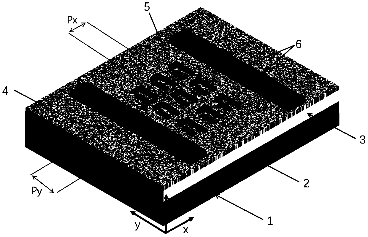
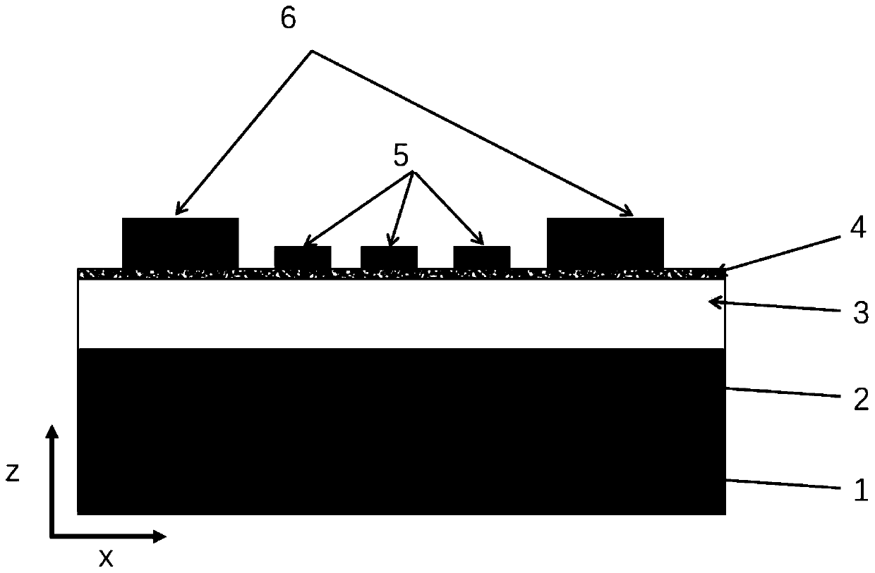
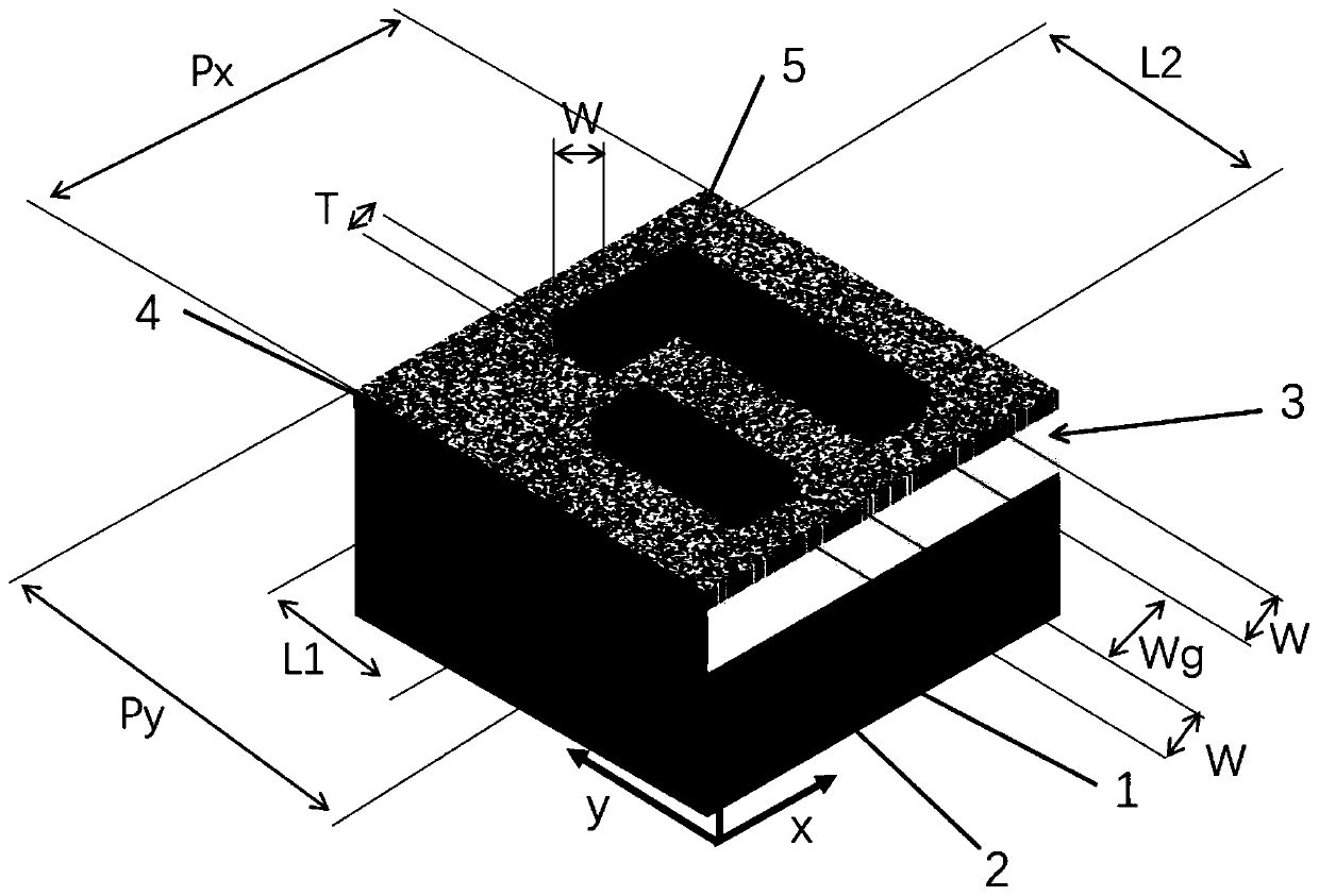
[0061] A microscopic image of a circularly polarized light detection device based on monolayer molybdenum diselenide and chiral surface plasmon metasurface as shown in Figure 4 shown. Device structure such as figure 1 and figure 2 As shown, it includes Si substrate 1 , Ag reflective layer 2 , SiO2 dielectric layer 3 , monolayer molybdenum diselenide 4 , chiral surface plasmon metasurface 5 and electrode 6 from bottom to top. Among them, the Ag reflective layer 2 is located above the Si substrate 1, and the SiO 2 The dielectric layer 3 is located above the Ag reflective layer 2, and the single-layer molybdenum disulphide selenide 4 after wet transfer is located on SiO 2 On the dielectric layer 3 , a chiral surface plasmon metasurface 5 generated by electron beam exposure is located on a monolayer of molybdenum diselenide 4 . The constituent material of the chiral surface plasmon metasurface 5 is gold, and its constituent unit is an asymmetric "η"-shaped nanostructure, su...


PUM


Abstract

The invention discloses a circularly polarized light detector and a preparation method thereof. The circularly polarized light detector comprises a substrate, a metal reflection layer, a dielectric layer, a single-layer transition metal chalcogenide, a chiral surface plasmon metasurface and an electrode, wherein the chiral surface plasmon metasurface integrated on the single-layer transition metalchalcogenide can generate selective absorption enhancement on incident circularly polarized light, therefore, the number of photon-generated carriers generated by the single-layer transition metal chalcogenide under the incident condition of circularly polarized light is modulated, measurable photocurrents of different sizes can be generated corresponding to different circularly polarized light under the action of external bias voltage, and photoelectric detection and distinguishing of different circularly polarized light are achieved. The circularly polarized light detector is an integratedphotoelectric detector for realizing a circularly polarized light detection function in a single planar device for the first time, works in a visible light waveband, and has the characteristics of ultra-thin thickness, high response speed and convenience in integration.

Description

technical field [0001] The present invention relates to a new type of photodetection device, in particular to a circularly polarized light detection device based on a single-layer transition metal chalcogenide and a chiral surface plasmon metasurface, which can be realized on a single planar photoelectric device. Photodetection of circularly polarized light. Background technique [0002] As a basic optical polarization state, circularly polarized light has a wide range of applications in optical communication, quantum optical technology, and biological and chemical sensing due to its unique physical properties. With the miniaturization and integration of optical systems, the traditional methods of detecting circularly polarized light through quarter-wave plates, polarizers, and photodetectors cannot be applied to small integrated optical systems. Therefore, realizing a small circularly polarized light detector that is easy to integrate has become an urgent problem to be sol...

Claims


Application Information

Patent Timeline
IPC IPC(8): H01L31/0224H01L31/0352H01L31/102H01L31/18
CPCH01L31/022408H01L31/0352H01L31/102H01L31/18Y02P70/50
Inventor 方哲宇蒋瞧杜博文
Owner PEKING UNIV
Why Eureka
Try Eureka