Two-phase composite microwave dielectric ceramic material for filter and preparation method thereof

A technology of microwave dielectric ceramics and filters, which is applied in the field of two-phase composite microwave dielectric ceramic materials for filters, can solve the problems of high temperature coefficient of resonance frequency, easy grain growth, high sintering temperature, etc., and achieve good dielectric properties and quality The effect of high factor and optimized material properties

Active Publication Date: 2020-05-19
SHANDONG SINOCERA FUNCTIONAL MATERIAL CO LTD
View PDF13 Cites 6 Cited by
  • Summary
  • Abstract
  • Description
  • Claims
  • Application Information

AI Technical Summary

Problems solved by technology

However, MgO-TiO 2 Due to the high temperature coefficient of resonant frequency (-55ppm/℃), easy...

Method used


Image

  • Two-phase composite microwave dielectric ceramic material for filter and preparation method thereof
  • Two-phase composite microwave dielectric ceramic material for filter and preparation method thereof
  • Two-phase composite microwave dielectric ceramic material for filter and preparation method thereof

Examples


Embodiment 1-11

[0035] Respectively according to the following table 1 (Mg 1-x-y Ca x co y ) 2 TiO 4 The structure and stoichiometric ratio of the material are MgO, CaO, CoO, TiO 2 Mix to obtain a mixture, and add water to mix according to the ratio of mixture: water mass ratio of 1:1.2, and add ammonium salt dispersant accounting for 0.8wt% of the total amount of the mixture, and use columnar zirconium balls for ball milling, The ball milling time is 3-5 hours to carry out preliminary mixing and dispersing of the materials, then place them in a sand mill, use zirconium balls with a diameter of 0.65mm as the grinding medium for further dispersion, and use a microwave dryer to dry until the moisture content is less than 1% after grinding. After the material is sieved with a pulverizer, it is calcined using a pusher furnace. The calcining temperature is 1155° C., and the holding time is 3 hours. The burned material is placed for subsequent use, and the (Mg 1-x-y Ca x co y ) 2 TiO 4 mat...

experiment example

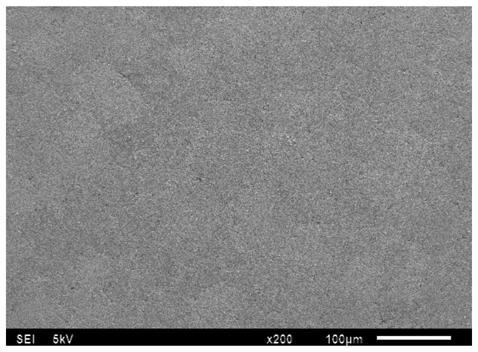
[0045] The above-mentioned granulated materials were respectively subjected to dry pressing molding, wherein, the electron microscope picture of the green body after the pressing of the material in Example 1 is shown in the attached figure 2 , it can be seen that the compactness of the green body after dry pressing is very good.

[0046] The above-mentioned granulated materials were respectively molded and sintered, and the sintering temperature of each green body was recorded, and the holding time was 4h, and the properties of the microwave dielectric ceramic materials prepared in the above-mentioned Examples 1-11 and Comparative Examples 1-3 were respectively analyzed. test. Test performance specifically includes:

[0047] 1) Using the dielectric resonant cavity method proposed by Hakki and Coleman to test the dielectric constant of the material, the f*Q value at 25°C, and the frequency temperature coefficient τf;

[0048] The frequency temperature coefficient τf means th...


PUM

PropertyMeasurementUnit
Dielectric constantaaaaaaaaaa

Abstract

The invention belongs to the technical field of microwave dielectric ceramic materials, particularly relates to a two-phase composite microwave dielectric ceramic material for a filter, and further discloses a preparation method of the two-phase composite microwave dielectric ceramic material. According to the two-phase composite microwave dielectric ceramic material disclosed by the invention, Mg2TiO4 is used as a main crystal form structure, Ca and Co elements are used for doping, and functional aids and/or sintering aids such as TiO2 and CaTiO3 are further added, so the microwave performance of the material is further optimized effectively. The composite microwave dielectric ceramic material is high in quality factor and has a dielectric constant of 18-23; the value of f*Q at 25 DEG C is larger than 60000; the value of the temperature coefficient of resonance frequency is close to zero, and use requirements of the filter can be met; meanwhile, the material also has relatively good dielectric property in a millimeter wave frequency band; and the sintering temperature of the material is only 1200-1300 DEG C, so low-temperature sintering performance is greatly improved, and large-scale stable production can be achieved.

Description

technical field [0001] The invention belongs to the technical field of microwave dielectric ceramic materials, in particular to a two-phase composite microwave dielectric ceramic material for filters, and further discloses a preparation method thereof. Background technique [0002] Microwave dielectric ceramics refer to ceramics that are used as dielectric materials in microwave frequency band (mainly UHF, SHF frequency band, 300MHz-300GHz) circuits and perform one or more functions. They have high dielectric constant, low dielectric loss, low Resonant frequency temperature coefficient and other excellent properties are important components of resonators, filters, duplexers, antennas, frequency stabilized oscillators, waveguide transmission lines and other devices, and can be widely used in personal portable mobile phones, microwave base stations, car phones, Satellite communication, military radar and many other fields. Especially in recent years, with the rapid developmen...

Claims


Application Information

Patent Timeline
IPC IPC(8): C04B35/465C04B35/626C04B35/64
CPCC04B35/465C04B35/62615C04B35/62695C04B35/64C04B2235/36C04B2235/442C04B2235/3217C04B2235/3224C04B2235/96
Inventor 杨月霞应红杨彬刘光明董鹏飞宋锡滨
Owner SHANDONG SINOCERA FUNCTIONAL MATERIAL CO LTD
Why Eureka
Try Eureka