
Tensile strain sensor and preparation method and application thereof

A tensile strain sensor technology, applied in the field of sensors, can solve the problems of only 65% ​​stretching range, low sensitivity, and small stretching range, and achieve the effects of high sensitivity, wide strain range, and large measurement range

Active Publication Date: 2020-06-16
SHENZHEN UNIV
View PDF7 Cites 1 Cited by
  • Summary
  • Abstract
  • Description
  • Claims
  • Application Information

AI Technical Summary

Problems solved by technology

However, there are still several problems with the strain sensor: a strain sensor with high sensitivity, but its stretching range is small; or a sensor with a wide stretching range, but its low sensitivity is very low
Chinese patent CN108332647A proposes a flexible piezoresistive strain sensor. Its main technical solution is to use metal glass film as the sensitive material. Although it has good linearity, its sensitivity coefficient is only 2.5
Chinese patent CN107655398A proposes a high-sensitivity stretchable flexible strain sensor. Its main technical solution is to use polymer to encapsulate the polyurethane sponge composite material covered by graphene and nickel film with cracks. Although the largest strain sensor The gage factor can reach 3300, but its stretch range is only 65%
In 2016, Shi et al. reported a graphene Strain sensor of sheet and silicone rubber composite material, when the sensor thickness is 10 μm, it has the largest gage factor value (164.5), but its tensile limit is 12%
Based on the above, stretchable strain sensors with high stretchability and sensitivity as well as good stability and durability are still a challenge.

Method used


Image

  • Tensile strain sensor and preparation method and application thereof
  • Tensile strain sensor and preparation method and application thereof
  • Tensile strain sensor and preparation method and application thereof

Examples


Embodiment 1

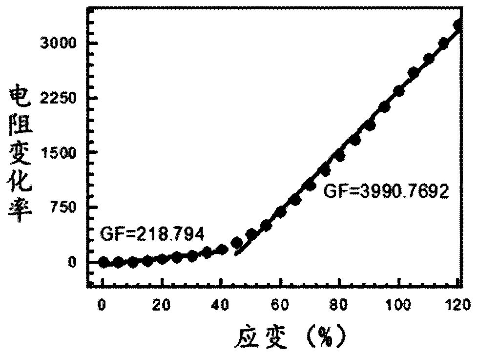
[0037] A stretchable strain sensor is obtained through a preparation method comprising the following steps, and the stretchable strain sensor has high sensitivity, high stretchability and wide strain range, as well as good stability and durability.

[0038] 1) Place a hollow polymer mask with a design pattern on the glass substrate (the design pattern is a square of 5cm*5cm);

[0039] 2) Deposit 1 mL of an ethanol solution with a concentration of 0.03 g / mL silver nanoparticles on a glass substrate containing a design pattern by the drop method, and then dry at 80 °C for 5 minutes to remove ethanol to provide a layer covered with conductive metal particles (silver nanoparticles). particle) base material, the mass per unit area of ​​conductive metal particles used in the preparation is 1.2mg / cm2 , the thickness of the conductive metal particles in the substrate covered with the conductive metal particles is about 10 microns;

[0040] 3) Spray 2 mL of the CNT dispersion with a co...

Embodiment 2

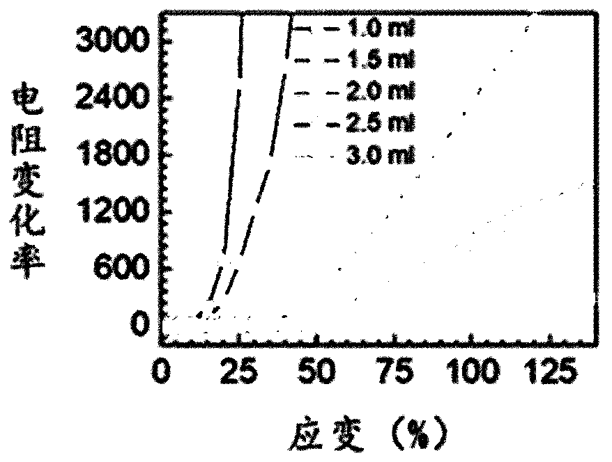
[0046] When measuring small strains, the strain sensor does not need a wide strain measurement range, and can appropriately reduce the volume consumption of the conductive carbon material, that is, reduce the thickness of the conductive carbon material layer. Example 2 uses a conductive metal particle dispersion with a concentration of 0.03 g / mL and a volume of 1 mL, that is, the mass per unit area of ​​the conductive metal particles used in the preparation is 1.2 mg / cm 2 . The concentration of the conductive carbon material dispersion is 5mg / mL, and the volume is 1mL, that is, the mass per unit area of ​​the conductive metal particles used in the preparation is 0.2mg / cm 2 . Other preparation steps and preparation conditions are the same as in Example 1. In step 2), the thickness of the conductive metal particles in the base material covered with conductive metal particles is about 10 microns. In step 3), the conductive carbon material and conductive metal particles are cover...

Embodiment 3

[0048] When measuring a larger strain, the strain sensor needs a larger strain detection range, and the volume consumption of the conductive carbon material can be appropriately increased, that is, the thickness of the conductive carbon material in the substrate covered with the conductive carbon material and conductive metal particles can be increased. Example 3 uses a conductive metal particle dispersion with a concentration of 0.03 g / mL and a volume of 1 mL, that is, the mass per unit area of ​​the conductive metal particles used in the preparation is 1.2 mg / cm 2 . The volume of the conductive carbon material dispersion is 3mL, the concentration is 5mg / mL, that is, the mass per unit area of ​​the conductive metal particles used in the preparation is 0.6mg / cm 2 . Other preparation steps and preparation conditions are the same as in Example 1. In step 2), the thickness of the conductive metal particles in the base material covered with conductive metal particles is about 10 ...


PUM

PropertyMeasurementUnit
thicknessaaaaaaaaaa
thicknessaaaaaaaaaa
thicknessaaaaaaaaaa

Abstract

The invention provides a tensile strain sensor and a preparation method and application thereof. The tensile strain sensor comprises a flexible substrate layer and a sensing layer. The sensing layer is partially embedded into the flexible substrate layer and comprises a conductive metal particle layer and a conductive carbon material layer, and the conductive carbon material layer is arranged between the flexible substrate layer and the conductive metal particle layer. Because of the self-locking effect at the interface of the double conductive sensing layers of the conductive carbon materiallayer and the conductive metal particle layer, a problem of continuous conduction of the strain material under large tensile strain is solved; and the sensor has the characteristics of high stretchability, high sensitivity, wide strain range, good stability and good durability.

Description

technical field [0001] The invention relates to the technical field of sensors, in particular to a stretchable strain sensor and its preparation method and application. Background technique [0002] Wearable electronic sensors have attracted extensive attention in the fields of human clinical diagnosis, health monitoring, human-machine interface, electronic skin, and intelligent robots. As an important member of electronic sensors, stretchable strain sensors have developed rapidly in recent years and can be used to detect various physiological activities of the human body, including large-scale bending movements of hands, arms, legs, etc. and deep breathing, swallowing, muscle vibration, blood pressure and pulse and other small-scale deformations. In particular, stretchable strain sensors for applications in biomechanics, physiology, and kinematics are required to have high sensitivity, wide strain range, and excellent durability. [0003] Among these requirements, high st...

Claims


Application Information

Patent Timeline
Patent Type & Authority Applications(China)
IPC IPC(8): G01B7/16A61B5/024A61B5/08A61B5/11A61B5/00G06K9/00G06F3/048
CPCG01B7/18A61B5/024A61B5/08A61B5/1107A61B5/1118A61B5/6801G06F3/048G06V40/174
Inventor 彭争春林婉儿王子娅管晓张琦
Owner SHENZHEN UNIV
Learn More