Marsh gas factory tail gas processing system

An exhaust gas treatment and factory technology, applied in gas treatment, combustion type, separation method, etc., can solve problems such as injury, environmental pollution, and surrounding public dissatisfaction with public health, and achieve the effect of avoiding white smoke and equipment corrosion

Inactive Publication Date: 2020-09-04
瑞必科净化设备(上海)有限公司
View PDF7 Cites 2 Cited by
  • Summary
  • Abstract
  • Description
  • Claims
  • Application Information

AI Technical Summary

Problems solved by technology

The existence of these substances not only pollutes the environment, but also causes dissatisfaction with the surrounding public and harms public health.

Method used


Image

  • Marsh gas factory tail gas processing system
  • Marsh gas factory tail gas processing system

Examples


Embodiment 1

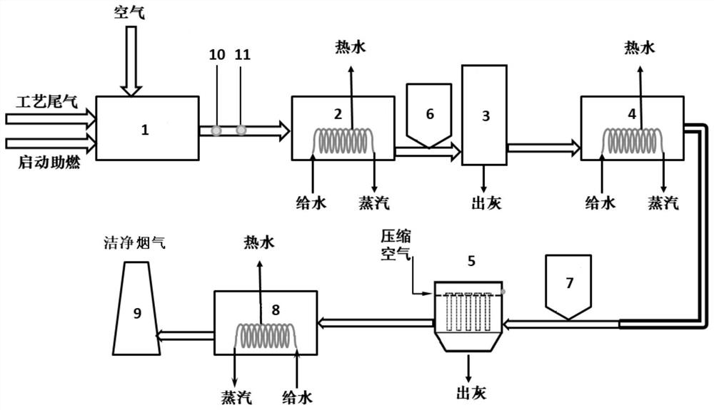
[0042] This embodiment provides a tail gas treatment system of a biogas plant, the treatment system includes an oxidation combustion device 1, a first waste heat recovery device 2, a desulfurization device 3, a second waste heat recovery device 4, a denitrification device 5, a first Three waste heat recovery devices 8 and a chimney 9;

[0043] An oxygen content measuring device 10 and a temperature measuring device 11 are sequentially arranged between the oxidation combustion device 1 and the first waste heat recovery device 2;

[0044] A desulfurization agent addition device 6 is provided between the first waste heat recovery device 2 and the desulfurization device 3 , and a denitration agent addition device 7 is provided between the second waste heat recovery device 4 and the denitration device 5 .

Embodiment 2

[0046] This embodiment provides a method for treating tail gas from a biogas plant, the method uses the tail gas treatment system of a biogas plant provided in Example 1, wherein the oxidation combustion device 1 is an oxidation furnace, the first waste heat recovery device 2, and the second waste heat recovery device 4 and the third waste heat recovery device 8 are waste heat boilers, gas-water heat exchangers or gas-gas heat exchangers, the desulfurization device 3 is a desulfurization reaction tower, and the denitrification device 5 is a ceramic fiber filter tube dust collector.

[0047] The treatment methods include:

[0048] The tail gas of the biogas factory enters the oxidation furnace for flameless combustion. When the oxidation furnace is started and ignited, biogas is used as an auxiliary fuel. The oxygen content measuring device 10 and the temperature measuring device 11 monitor the flue gas treated by the oxidation furnace; Enter the waste heat boiler for waste hea...

Embodiment 3

[0050] This embodiment provides a method for treating tail gas from a biogas factory, the method uses the tail gas treatment system of a biogas factory provided in Example 1, wherein the oxidation combustion device 1 is a thermal storage oxidation furnace, the first waste heat recovery device 2, the second waste heat The recovery device 4 and the third waste heat recovery device 8 are waste heat boilers, the desulfurization device 3 is a desulfurization reaction tower, and the denitrification device 5 is a ceramic fiber filter tube dust collector.

[0051] The treatment methods include:

[0052] The tail gas from the biogas factory enters the regenerative oxidation furnace for flameless combustion. When the regenerative oxidation furnace is started and ignited, biogas is used as an auxiliary fuel. The oxygen content measuring device 10 and the temperature measuring device 11 monitor the flue gas treated by the regenerative oxidation furnace; The flue gas treated by the thermal...


PUM


Abstract

The invention provides a marsh gas factory tail gas processing system, which comprises an oxidation combustion device, a first waste heat recovery device, a desulfurization device, a second waste heatrecovery device, a denitration device and a third waste heat recovery device, wherein the oxidation combustion device, the first waste heat recovery device, the desulfurization device, the second waste heat recovery device, the denitration device and the third waste heat recovery device are connected in sequence. The service life of the ceramic fiber filter tube of the tail gas processing systemcan be as long as 7-10 years. Since the device system works at a high temperature during a section with nitrogen oxide and sulfur oxide, and therefore, equipment corrosion caused by condensation is avoided.

Description

technical field [0001] The invention belongs to the field of tail gas treatment and relates to a tail gas treatment system of a biogas factory. Background technique [0002] With the public's increasing requirements for environmental protection, the demand for green renewable energy has increased, and it has benefited from the promotion of national energy policies. Biomass energy has become an important supplementary energy source, among which biogas purification to produce bio-natural gas will be greatly developed. However, these purification plants often encounter the problems of odor treatment and purification process tail gas during operation. If this problem is not resolved, new pollution and greenhouse gases will be introduced in the environmental protection treatment of biogas (the greenhouse gas effect of methane in tail gas is 25 times that of carbon dioxide under the same quality). The tail gas of this purification process must be treated for the two commonly use...

Claims


Application Information

Patent Timeline
Patent Type & Authority Applications(China)
IPC IPC(8): F23G7/06F23G5/46B01D53/50B01D46/24B01D53/86
CPCF23G7/06F23G7/068F23G5/46B01D53/508B01D53/8637B01D46/24B01D53/8662B01D2257/2064
Inventor 程鹏
Owner 瑞必科净化设备(上海)有限公司
Why Eureka
Try Eureka