Supercharge Your Innovation With Domain-Expert AI Agents!

STED super-resolution microscopic imaging device based on multi-fiber optical tweezers

A microscopic imaging and super-resolution technology, applied in the field of photonics, can solve problems such as the difficulty of optical power distribution control, the decrease of particle control accuracy, and low stability, so as to improve system integration, easy processing, and avoid external interference. Effect

Active Publication Date: 2020-09-11
GUILIN UNIV OF ELECTRONIC TECH
View PDF16 Cites 8 Cited by
  • Summary
  • Abstract
  • Description
  • Claims
  • Application Information

AI Technical Summary

Problems solved by technology

For example, the Chinese patent CN211817464U proposes a super-resolution fluorescence microscopy device based on tangential polarization. Although a good microscopic illumination effect is obtained, the realization of this effect requires complex optical paths, expensive precision instruments, and the stability is not very high.
Chinese patent CN103617330A proposes a super-resolution STED microscopic imaging device excited by a broadband laser light source generated by a supercontinuum. Although the function of synchronous adjustment of the two lasers is improved to achieve good microscopic illumination, the overall optical path is complicated
However, it is more complicated to analyze the light field of a single multi-core fiber converging at the fiber end, so the control accuracy of the particles is greatly reduced. Due to the complex core structure of the multi-core fiber, the optical power between the light source injection and multiple cores Allocation control is also very difficult
In addition, the multi-core optical fiber or ring core proposed in the research has a high cost of drawing and is not easy to purchase

Method used


Image

  • STED super-resolution microscopic imaging device based on multi-fiber optical tweezers
  • STED super-resolution microscopic imaging device based on multi-fiber optical tweezers
  • STED super-resolution microscopic imaging device based on multi-fiber optical tweezers

Examples


Embodiment Construction

[0031] The present invention will be further described below in conjunction with the accompanying drawings as an example.

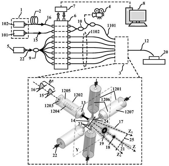
[0032] combine figure 1 , the embodiment of the present invention is that the captured light 22 output by the laser 5 is input into the core 1206 of a plurality of single-core optical fibers 1201 through the optical power control module 6, and then a plurality of free transmission light beams 23 are output at the fiber ends of the plurality of single-core optical fibers 1201 , and stably capture the microsphere lens 14 three-dimensionally. On the one hand, the excitation light 15 output by the laser 101 is injected into the central double-clad core 1203 after passing through the optical power control module 6 and two 1×2 broadband fiber couplers 10, since the excitation light 15 will not be transmitted by the spiral grating 1204 Therefore, it is directly emitted from the fiber end of the double-clad optical fiber 1202 and is focused by the microsphere le...


PUM


Abstract

The invention provides a STED super-resolution microscopic imaging device based on multi-fiber optical tweezers. The device is characterized by comprising a laser for STED imaging, a delay unit, a light beam generator, an imaging display instrument, a laser for controlling a microsphere lens, an optical power control module, a feedback control module, a computer, an optical fiber coupler and a plurality of single-mode optical fibers. According to the invention, based on the modulation effect of the spiral grating in the double-clad optical fiber and the time delay effect of the time delay unit, stimulated emission loss of two laser beams occurs on the surface of a fluorescent sample, and single-point super-resolution microscopic imaging is realized. A plurality of single-core optical fibers positioned on the same plane are adopted to capture the microsphere lens and accurately and controllably move the microsphere lens on a two-dimensional plane, so that'full-plane 'super-resolution microscopic imaging of a fluorescent sample is realized. The invention has the advantages that: the flexibility and the integration level of the conventional STED imaging device are improved, so that the STED imaging device can be suitable for micro-scale endoscopic multidirectional super-resolution imaging.

Description

[0001] (1) Technical field [0002] The present invention relates to a STED super-resolution microscopic imaging device based on multi-fiber optical tweezers, mainly relates to the technical field of photonics, and more specifically relates to a fiber STED super-resolution imaging method and device. [0003] (2) Background technology [0004] Due to the diffraction limit of the resolution of traditional fluorescence microscopes, some super-resolution imaging techniques that break through the diffraction limit of resolution have been developed in the past decade, such as stimulated emission depletion microscopy (STED), structured illumination microscopy (SIM), etc. ), photoactivated localization microscopy (PALM), stochastic optical reconstruction microscopy (STORM), etc. Among them, STED is based on the laser scanning confocal fluorescence microscope, which introduces another ring-shaped depletion light with a wavelength longer than the excitation light. A focused laser beam e...

Claims


Application Information

Patent Timeline
IPC IPC(8): G21K1/00G02B6/26G02B21/00G01N21/64
CPCG21K1/006G02B6/262G02B21/0032G02B21/0076G01N21/6458
Inventor 邓洪昌王瑞苑立波
Owner GUILIN UNIV OF ELECTRONIC TECH
Features
  • R&D
  • Intellectual Property
  • Life Sciences
  • Materials
  • Tech Scout
  • Unparalleled Data Quality
  • Higher Quality Content
  • 60% Fewer Hallucinations
Learn More