Laser frequency stabilization device based on delay differential feedforward and method thereof

A delay differential, laser technology, applied in the direction of lasers, laser components, phonon exciters, etc., can solve the problem of difficulty in miniaturization and integration, inability to linearly modulate optical frequency stabilization and linearity improvement, and laser frequency instability, etc. question

Inactive Publication Date: 2021-07-06
AEROSPACE INFORMATION RES INST CAS
View PDF4 Cites 5 Cited by
  • Summary
  • Abstract
  • Description
  • Claims
  • Application Information

AI Technical Summary

Problems solved by technology

[0003] Due to the internal noise of the laser, such as spontaneous radiation noise, excitation power noise, etc., and external influences, such as temperature, vibration, and atmospheric changes, many factors will cause changes in the internal cavity length of the laser, resulting in instability of the laser frequency.
Traditional frequency stabilization methods include saturation absorption frequency stabilization, wavelength modulation frequency stabilization, modulation spectrum frequency stabilization, modulation transfer spectrum frequency stabilization, two-color laser frequency stabilization, and frequency-voltage conversion frequency stabilization, etc., but these methods either introduce additional noise, or chain The problem is complicated and expensive, and the feedback technology is used. There is no way to achieve real-time correction. At the same time, it can only achieve frequency stabilization of single-frequency lasers, and cannot be used for frequency stabilization and linearity improvement of chirp light. Ease of miniaturization and integration

Method used


Image

  • Laser frequency stabilization device based on delay differential feedforward and method thereof
  • Laser frequency stabilization device based on delay differential feedforward and method thereof
  • Laser frequency stabilization device based on delay differential feedforward and method thereof

Examples


Embodiment Construction

[0025] Hereinafter, embodiments of the present disclosure will be described with reference to the drawings. It should be understood, however, that these descriptions are exemplary only, and are not intended to limit the scope of the present disclosure. In the following detailed description, for purposes of explanation, numerous specific details are set forth in order to provide a thorough understanding of the embodiments of the present disclosure. It may be evident, however, that one or more embodiments may be practiced without these specific details. Also, in the following description, descriptions of well-known structures and techniques are omitted to avoid unnecessarily obscuring the concepts of the present disclosure.

[0026] The terminology used herein is for the purpose of describing particular embodiments only, and is not intended to be limiting of the present disclosure. The terms "comprising", "comprising", etc. used herein indicate the presence of stated features,...


PUM


Abstract

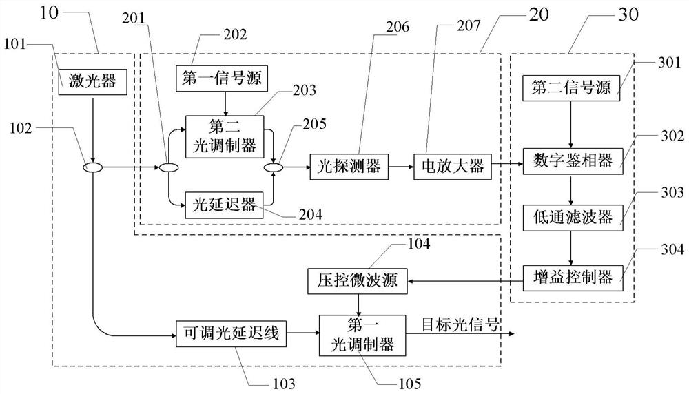
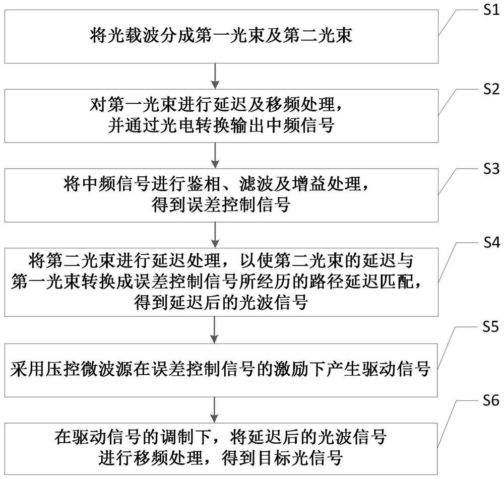
The invention provides a laser frequency stabilization device based on delay differential feed-forward, and the device comprises: an optical signal generation unit which comprises an optical coupler which is used for dividing an optical carrier wave into two light beams; a delay difference unit which is used for carrying out delay and frequency shift processing on the first light beam and outputting an intermediate frequency signal through photoelectric conversion; a phase lock control unit which is used for performing phase discrimination, filtering and gain processing on the intermediate frequency signal to obtain an error control signal; an optical signal generation unit which further comprises an adjustable optical delay line which is used for carrying out delay processing on the second light beam so as to enable the delay of the second light beam to be matched with the path delay experienced by converting the first light beam into the error control signal, and a delayed optical wave signal is obtained; a voltage-controlled microwave source which is used for generating a driving signal under the excitation of the error control signal; and a light modulator which is used for performing frequency shift processing on the delayed light wave signal under the modulation of the driving signal to obtain a target light signal. The invention further provides a laser frequency stabilization method based on delay differential feedforward.

Description

technical field [0001] The present disclosure relates to the fields of coherent communication and laser radar, in particular to a laser frequency stabilization device and method based on delayed differential feedforward. Background technique [0002] Today, the ever-increasing Internet traffic has led to a surge in demand for high-speed optical fiber transmission systems with bit rates of 100Gbit / s and beyond. Higher-order modulation and digital coherent detection are considered as promising technologies to improve the capacity and spectral efficiency of next-generation optical fiber networks. Therefore, the requirements for high-frequency-stability light sources become more stringent when denser constellations are applied. In addition, other applications such as fiber optic sensing, phased array antenna systems, and coherent lidar systems also require high frequency stable light sources. [0003] Due to the internal noise of the laser, such as spontaneous radiation noise,...

Claims


Application Information

Patent Timeline
Patent Type & Authority Applications(China)
IPC IPC(8): H01S3/13H01S3/137H04B10/50
CPCH01S3/13H01S3/137H04B10/50595H04B10/5059H04B10/50597
Inventor 李王哲张祥鹏
Owner AEROSPACE INFORMATION RES INST CAS
Why Eureka
Try Eureka