Self-crimping intravascular stent forming system and forming method
A vascular stent and collection system technology, which is applied in the fields of mechanical manufacturing and biological manufacturing, can solve problems such as the layered structure of difficult stents, and achieve the effects of high stent strength, improved efficiency and quality assurance
- Summary
- Abstract
- Description
- Claims
- Application Information
AI Technical Summary
Problems solved by technology
Method used
Image
Examples
Embodiment 1
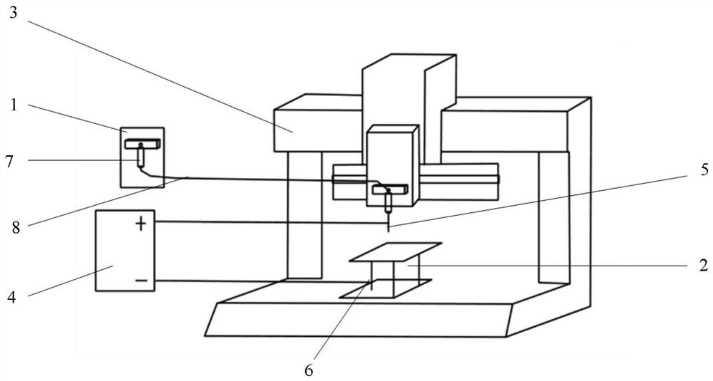
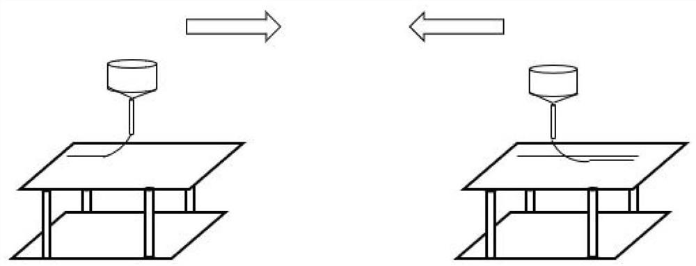
[0057] see Figure 1-Figure 2 , a layered vascular stent forming system based on electrostatic direct writing technology, including a feeding system 1, a spinning collection system 2, a three-axis motion platform 3, and a power supply 4. The feeding system 1 is directly connected to the syringe of the needle; the spinning The collection system 2 is fixedly installed on the XY-axis platform of the three-axis motion platform 3 , the positive pole of the power supply 4 is connected to the metal part of the syringe needle 5 , and the negative pole is connected to the metal part of the spinning collector 6 .
Embodiment 2
[0059] Embodiment 2 is basically the same as Embodiment 1, the difference is only in:
[0060] The feeding system 1 includes a micropump syringe 7 and a connecting conduit 8, and the micropump actuator is driven by the micropump controller to push the syringe piston cylinder to extrude the spinning material;
[0061] The spinning collection system 2 is fixedly connected to the XY axis plane of the three-axis motion platform 3, the positive pole of the power supply 4 is connected to the metal part of the syringe needle 5, and the negative pole is connected to the metal part of the spinning collector 6, so that the syringe needle 5 and the spinning collection system 2 to form a high-voltage electric field.
Embodiment 3
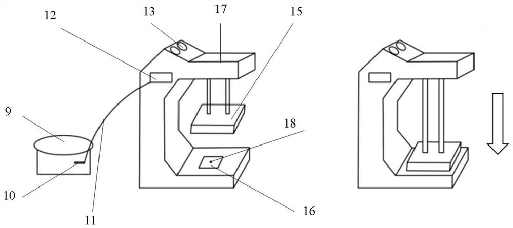
[0063] see image 3 , a film preparation method based on micro-imprinting technology, comprising an air pump 9, an embossing machine 17, and a temperature control system 13, the air pump 9 is directly connected to the imprinting machine 17 through a conduit 11, the air pump 9 is connected with an air pressure control valve 10, and the air pressure The control valve 10 is used to adjust the feed air pressure, thereby further controlling the up and down movement of the heating plate 15; the temperature control system 13 directly controls the surface temperature of the heating plate 15, and through the temperature control system 13, the duration of imprinting can be controlled.
PUM
 Abstract
Description
Claims
Application Information
 - R&D
- Intellectual Property
- Life Sciences
- Materials
- Tech Scout
- Unparalleled Data Quality
- Higher Quality Content
- 60% Fewer Hallucinations
Browse by: Latest US Patents, China's latest patents, Technical Efficacy Thesaurus, Application Domain, Technology Topic, Popular Technical Reports.
© 2025 PatSnap. All rights reserved.Legal|Privacy policy|Modern Slavery Act Transparency Statement|Sitemap|About US| Contact US: help@patsnap.com


