
Laser-assisted positive electrode interface layer construction method

A laser-assisted, interface layer technology, applied in the direction of positive electrodes, laser welding equipment, structural parts, etc., can solve the problems of limited thermal stability of pole pieces, unfavorable commercial applications, difficult to apply pole pieces, etc., to avoid interface side effects. Reaction, avoid high temperature heating process, the effect of fast processing

Active Publication Date: 2022-01-14
NORTHWESTERN POLYTECHNICAL UNIV
View PDF15 Cites 2 Cited by
  • Summary
  • Abstract
  • Description
  • Claims
  • Application Information

AI Technical Summary

Problems solved by technology

However, limited by the thermal stability of the pole piece itself, the traditional positive electrode coating method can only be used for active materials, and it is difficult to apply it to the pole piece.
Gas-phase reaction methods, such as atomic layer deposition, can achieve uniform coating of the entire electrode surface, (Liang, J. et al. Nano Energy 78, 105107 (2020)), but its high cost is not conducive to large-scale commercial applications

Method used


Image

  • Laser-assisted positive electrode interface layer construction method
  • Laser-assisted positive electrode interface layer construction method
  • Laser-assisted positive electrode interface layer construction method

Examples


Embodiment 1

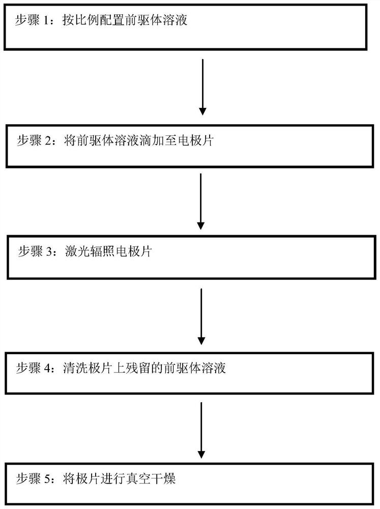
[0036] Step 1, configuring the precursor solution, the volume ratio of tris(trimethylsilane) phosphate to solvent DEC is 10%;

[0037] Step 2. Add 40 μL cm of the precursor solution dropwise to the positive electrode -2 ;

[0038] Step 3. Irradiate the pole piece with pulsed laser, the laser power is 40mJ cm -2 , the frequency is 50HZ, and the irradiation time is 4 minutes;

[0039] Step 4, using diethyl carbonate (DEC) to clean the remaining precursor solution on the pole piece;

[0040] Step 5, vacuum-drying the pole piece obtained in step 4 at 60°C;

[0041] Charge and discharge performance test:

[0042] Put the positive electrode sheet obtained in Example 1 of the present invention in a glove box filled with high-purity argon gas, with water and oxygen concentrations less than 0.1ppm, and use metal lithium sheet as the negative electrode, according to the negative electrode shell, lithium sheet, electrolyte, positive electrode sheet, steel Sheets, shrapnel, and the a...

Embodiment 2

[0047] Step 1, configuring the precursor solution, the volume ratio of tris(trimethylsilane) phosphate to solvent DEC is 20%;

[0048] Step 2. Add 1 mL of precursor solution dropwise to the positive electrode. -2 ;

[0049]Step 3. Irradiate the pole piece with pulsed laser, the laser power is 50mJ cm -2 , the frequency is 60HZ, and the irradiation time is 10 minutes;

[0050] Step 4, using diethyl carbonate (DEC) to clean the remaining precursor solution on the pole piece;

[0051] Step 5, vacuum-drying the pole piece obtained in step 4 at 70°C;

Embodiment 3

[0053] Step 1, configuring the precursor solution, the volume ratio of tris(trimethylsilane) borate to solvent DEC is 2%;

[0054] Step 2. Add 20 μL cm of the precursor solution dropwise to the positive electrode -2 ;

[0055] Step 3. Irradiate the pole piece with pulsed laser, the laser power is 200mJ cm -2 , the frequency is 20HZ, and the irradiation time is 2 minutes;

[0056] Step 4, using diethyl carbonate (DEC) to clean the remaining precursor solution on the pole piece;

[0057] Step 5, vacuum-drying the pole piece obtained in step 4 at 120°C;


PUM


Abstract

The invention relates to a laser-assisted positive electrode interface layer construction method, which is characterized in that a specific precursor solution is decomposed on the surface of an electrode and deposited on the surface of the electrode through pulse laser irradiation, electrolyte decomposition and interface side reaction are inhibited, and the cycling stability is improved. The method is characterized in that an additive in a precursor solution is induced by pulse laser to be decomposed on the surface of a positive electrode to realize construction of a positive electrode protection layer, wherein the pulse laser power is 20-200 mJ cm<-2>, the electrode area corresponding to the use amount of the precursor solution is 20 [mu] L<-1> mL cm<-2>, and the laser wavelength is 1064 cm<-1>. Due to locality of laser heating, the additive with relatively good thermal stability can be decomposed on the surface of the electrode plate without damaging the electrode structure, so that the electrode is protected. The construction method for the positive electrode protection layer can be used for large-scale production, and is simple to operate and low in cost.

Description

technical field [0001] The invention belongs to the technical field of lithium ion battery preparation, and relates to a laser-assisted positive electrode interface layer construction method. Background technique [0002] With the rapid development of electric vehicles, insufficient cruising range has gradually become an important factor restricting the popularization of pure electric vehicles to the public. Among them, the energy density of the power battery is the key that directly affects the cruising range of electric vehicles. In the current power battery cathode material system, the use of high-voltage cathodes to increase energy density has gradually become the development trend of the industry. For example, the charging upper limit voltage of ternary materials in half-cells is generally 4.3V, and the charging cut-off voltage of some materials is even as high as 4.5V, which is beyond the application range of traditional formula electrolytes. Therefore, the applicati...

Claims


Application Information

Patent Timeline
IPC IPC(8): H01M4/139H01M4/62H01M10/0525B23K26/352
CPCH01M4/139H01M4/628H01M10/0525B23K26/352H01M2004/028Y02E60/10
Inventor 马越汤晓宇白苗
Owner NORTHWESTERN POLYTECHNICAL UNIV
Learn More