Biomass combined heat and power generation flue gas waste heat recycling system and method

A technology for co-generation of heat and power and waste heat from flue gas, which is applied in heat recovery systems, biochemical equipment and methods, heating systems, etc. The effect of improving the utilization rate of heat energy and reducing energy consumption

Pending Publication Date: 2022-01-21
吉林宏日新能源股份有限公司
View PDF0 Cites 2 Cited by
  • Summary
  • Abstract
  • Description
  • Claims
  • Application Information

AI Technical Summary

Problems solved by technology

[0006] This application is to solve the technical problems of latent heat recovery of low-grade flue gas formed after biomass power generation and heat supply, heat pump quality improvement and low-grade waste heat absorption
Aiming at the problems of low comprehensive fuel utilization rate, high moisture content, and large exhaust heat loss of biomass cogeneration system

Method used


Image

  • Biomass combined heat and power generation flue gas waste heat recycling system and method
  • Biomass combined heat and power generation flue gas waste heat recycling system and method
  • Biomass combined heat and power generation flue gas waste heat recycling system and method

Examples


Embodiment Construction

[0031] A schematic diagram of a layer structure according to an embodiment of the invention is shown in the drawing. The figures are not drawn to scale, with certain details exaggerated and possibly omitted for clarity. The shapes of the various regions and layers shown in the figure, as well as their relative sizes and positional relationships are only exemplary, and may deviate due to manufacturing tolerances or technical limitations in practice, and those skilled in the art will Regions / layers with different shapes, sizes, and relative positions can be additionally designed as needed.

[0032] Apparently, the described embodiments are some, but not all, embodiments of the present invention. Based on the embodiments of the present invention, all other embodiments obtained by persons of ordinary skill in the art without making creative efforts belong to the protection scope of the present invention. In the description of the present invention, it should be noted that the te...


PUM


Abstract

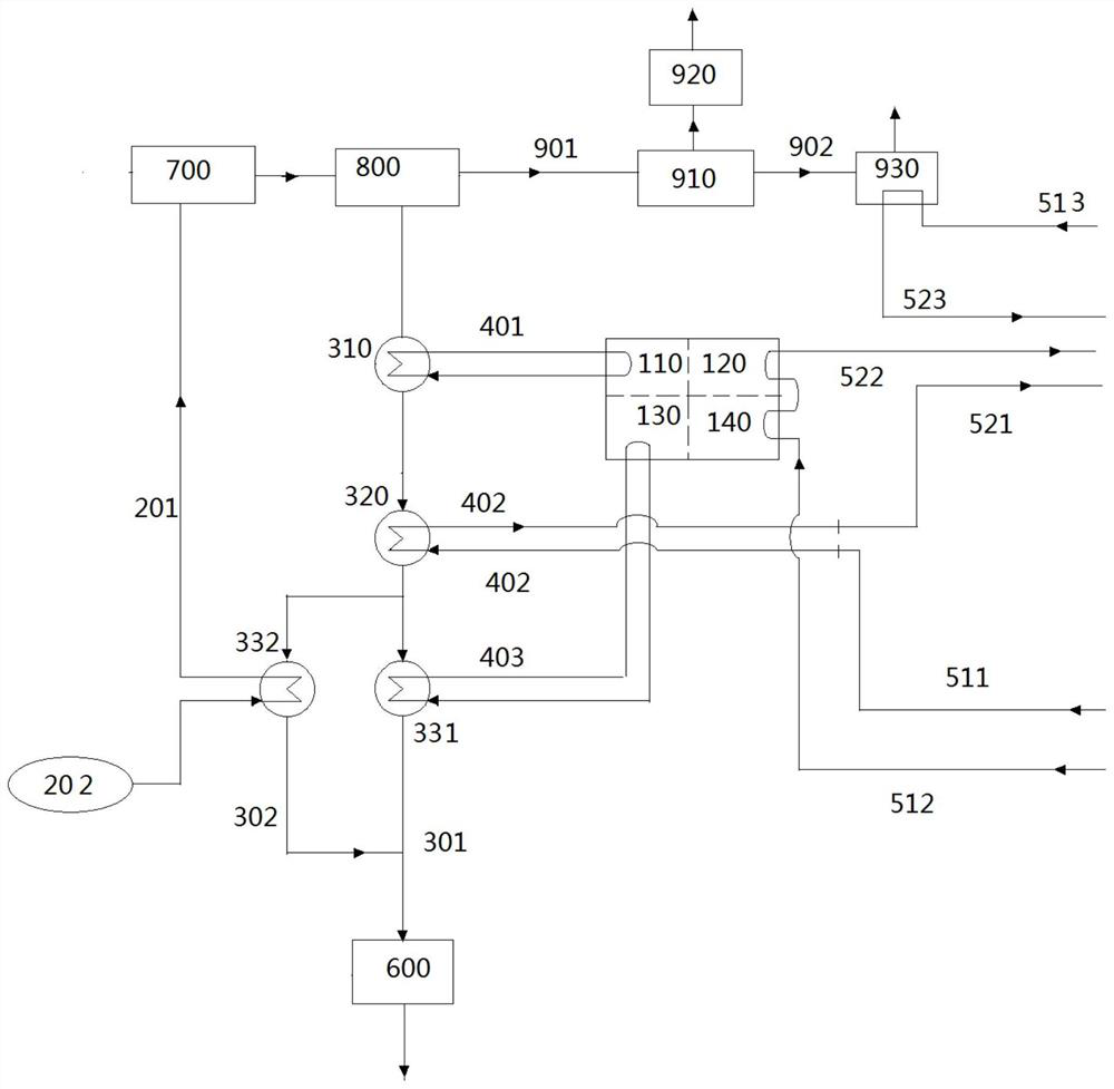
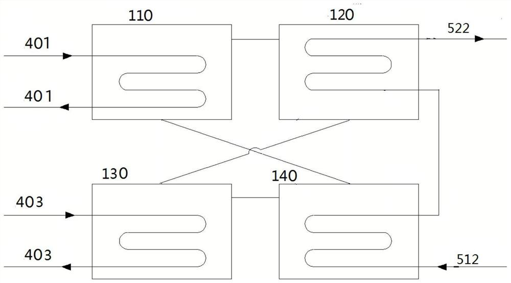
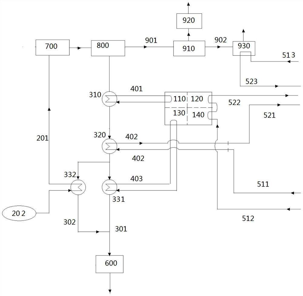
The invention discloses a biomass combined heat and power generation flue gas waste heat recycling system. Flue gas sequentially enters a first-stage heat exchanger (310), a second-stage heat exchanger (320) and a third-stage heat exchanger (330) through a smoke exhaust pipe (301) to heat primary waste heat water and third-stage waste heat water in a first-stage waste heat water circulating pipe (401) and a third-stage waste heat water circulating pipe (403), and finally the flue gas is discharged into a biogas digester; the primary waste heat water enters an absorption heat pump generator (110) to be cooled; the third-stage waste heat water enters an absorption heat pump evaporator (130) to be cooled; heat supply network water enters the second-stage heat exchanger (320) through a heat supply network water first return pipe (511) and a second-stage waste heat water circulating pipe (402) to be heated and then is converged into a heat supply network; the heat supply network water sequentially enters an absorption heat pump absorber (140) and an absorption heat pump condenser (120) through a second heat supply network water return pipe (512) to be heated and then is converged into the heat supply network; and external air (200) enters a third-stage heat exchanger second unit (332) through an air inlet pipe (201) to be heated and then enters a drying device (700).

Description

technical field [0001] The invention belongs to the technical field of heat energy recovery, and specifically relates to a system and method for recovering and utilizing waste heat of flue gas from cogeneration of biomass heat and power. Background technique [0002] In the biomass direct combustion power generation system, the moisture content of the fuel is high, the moisture content of the flue gas is large, the heat loss of the exhaust gas is large, and the comprehensive utilization rate is low. There are usually temperature gaps in the utilization of flue gas waste heat, and it is impossible to realize the "cascade utilization" and "consumption and exhaustion" of flue gas energy. [0003] In view of the above problems, combined with the actual operation of biomass direct-fired power plants, following the principle of "corresponding temperature and grade, energy cascade utilization", the cascade recovery of flue gas waste heat was carried out. [0004] In view of the ac...

Claims


Application Information

Patent Timeline
Patent Type & Authority Applications(China)
IPC IPC(8): F24D3/18F26B21/00C12M1/107C12M1/02C12M1/00F01D15/10F01K17/02
CPCF24D3/18F26B21/002C12M21/04C12M41/20F01D15/10F01K17/02F24D2200/126F24D2200/123Y02E20/14Y02E50/30Y02B30/52Y02P70/10
Inventor 洪浩王震坤田晓霞隋海然张志鑫刘菲陈壹杰冯雨
Owner 吉林宏日新能源股份有限公司
Why Eureka
Try Eureka