
A High Brightness Main Oscillation Power Amplified Picosecond Laser System

A power amplification and picosecond laser technology, which is applied to lasers, laser devices, laser components, etc., can solve the problems that crystals cannot withstand high power, end-pump pumping power density is high, and multi-stage amplifier structures are required to achieve Effects of improved beam quality, simplified structure, easy integration and disassembly

Active Publication Date: 2022-07-08
LASER RES INST OF SHANDONG ACAD OF SCI
View PDF7 Cites 0 Cited by
  • Summary
  • Abstract
  • Description
  • Claims
  • Application Information

AI Technical Summary

Problems solved by technology

Generally, solid-state amplifiers include two types, one is a diode-pumped solid gain medium regenerative amplifier, which can provide high gain, but the structure is complex and expensive; the other is a traveling wave amplifier, which uses a multi-pass solid gain medium Directly amplify the low-power laser seed source, with simple structure and easy implementation. This type of laser is divided into end-pump and side-pump according to the pumping method
[0005] The pump power density of the end pump is high, which can achieve good mode matching between the pump light and the oscillating light, and can achieve high gain with a short gain medium length. The representative crystal has Nd:YVO 4 , Nd:GdVO 4 The disadvantage is that the crystal cannot withstand high power and requires a multi-stage amplifier structure, which increases the complexity of the system; the advantage of side pumping is that it will not easily burst when pumping at high power, and the water cooling power of the module can reach several kilowatts Commonly used crystals include Nd:YAG, Yb:YAG, etc., but the main problem faced by this type of method is the thermal spherical aberration effect of the gain, that is, the beam quality is difficult to control, which affects the brightness of the final output laser

Method used


Image

  • A High Brightness Main Oscillation Power Amplified Picosecond Laser System
  • A High Brightness Main Oscillation Power Amplified Picosecond Laser System
  • A High Brightness Main Oscillation Power Amplified Picosecond Laser System

Examples


Embodiment 1

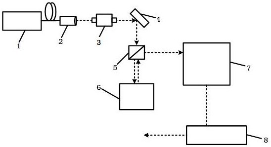
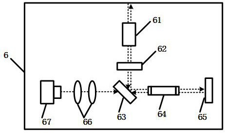
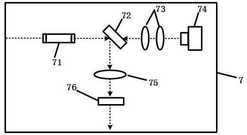
[0038] The invention provides a high-brightness main oscillation power amplifying picosecond laser system, such as figure 1 As shown, it includes an all-polarization-maintaining fiber picosecond seed laser 1, a fiber collimator 2, a space isolator 3, a 45° total reflection mirror 4, a polarization beam splitter prism 5 (PBS), a first-class solid Traveling wave amplifier 6, two-stage solid-state traveling wave amplifier 7 and three-stage solid-state traveling-wave amplifier 8, one-stage solid-state traveling wave amplifier 6 is located on the transmitted light side of polarization beam splitter prism 5, and two-level solid-state traveling wave amplifier 7 is located at polarization beam splitter prism 5 the reflected light side.

[0039] All polarization-maintaining fiber picosecond seed laser 1, for generating picosecond pulsed laser at 1064 nm wavelength, pulse width 100 nJ, repetition rate adjustment range 10 kHz-20 MHz.

[0040] The fiber collimator 2 pigtail is connected...

Embodiment 2

[0070] The invention also provides a high-brightness main oscillation power amplifying picosecond laser system, such as Figure 5 As shown, on the basis of the structure of Embodiment 1, a frequency multiplication module 9 is also set after the three-stage solid-state traveling wave amplifier 8 . like Image 6 As shown, the frequency doubling module 9 includes a second lens 91, a frequency doubling crystal 921, a third lens 93, a fourth 45° dichroic mirror 94 and a A laser absorber 95 is arranged on the side, and the frequency-doubling crystal 921 is wrapped with an indium foil with a thickness of 0.05 mm and placed in a fixture 922 to ensure close contact. The material of the fixture 922 can be selected from red copper. The fixture 922 is connected to the temperature control module 923 . The temperature control module 923 can use a semiconductor refrigerator (Thermo Electric Cooler, TEC), and mainly changes the temperature of the fixture 922, so as to precisely control the ...


PUM

PropertyMeasurementUnit
thicknessaaaaaaaaaa
optical damage thresholdaaaaaaaaaa
wavelengthaaaaaaaaaa

Abstract

The invention belongs to the technical field of ultrafast lasers, and discloses a high-brightness main oscillation power amplifying picosecond laser system, comprising an all-polarization-maintaining fiber picosecond seed laser, a fiber collimator, a space isolator, 45° total reflection mirror, polarization beam splitter prism, one-stage solid-state traveling wave amplifier, two-stage solid-state traveling wave amplifier and three-stage solid-state traveling wave amplifier, the first-stage solid-state traveling wave amplifier is located on the transmitted light side of the polarization beam splitter The wave amplifier is located on the reflected light side of the polarization beam splitter prism, and the fiber collimator is connected to the all polarization maintaining fiber picosecond seed laser through the pigtail. The picosecond laser system disclosed by the invention has the advantages of simple structure, stable performance and easy maintenance, and can realize high-brightness 1064 nm laser output. By setting up a frequency doubling module that is easy to integrate and disassemble, based on 100W fundamental frequency light, it can achieve more than 50 W The green light output can meet the needs of a wide range of industrial applications.

Description

technical field [0001] The invention belongs to the technical field of ultrafast lasers, and particularly relates to a high-brightness main oscillation power amplifying picosecond laser system. Background technique [0002] In recent years, high-brightness picosecond lasers have been widely used in micromachining, precision ranging, medicine and spectroscopy due to their advantages of high spectral purity and high peak power. They are also commonly used pumps in nonlinear optical frequency conversion applications. Pu light source. The short duration of the interaction between the picosecond pulse and the material can avoid the effects of laser linear absorption, energy transfer and diffusion, thereby realizing the "cold processing" of the material. [0003] In order to achieve high-brightness picosecond laser output, fiber laser systems can exhibit very high gain and low threshold. The disadvantage is that high peak power often causes optical damage and produces obvious non...

Claims


Application Information

Patent Timeline
Patent Type & Authority Patents(China)
IPC IPC(8): H01S3/094H01S3/139H01S3/23
CPCH01S3/091H01S3/139H01S3/094H01S3/23H01S3/094042H01S3/10061H01S3/0064H01S3/2316H01S3/005H01S3/06712H01S3/09415H01S3/0085H01S3/1611
Inventor 刘民哲赵坤刘梦霖王丽莎李欢欣翟瑞占贾中青张振振
Owner LASER RES INST OF SHANDONG ACAD OF SCI
Learn More