Catalytic distillation process for olefin production device
A production device and a technology for catalytic rectification, which are applied in the fields of catalytic rectification and selective hydrogenation of carbon three highly unsaturated hydrocarbon components, and carbon two, and can solve the problem of poor gas-liquid flow conditions, uneven catalyst distribution, and bed pressure drop. too big problem
- Summary
- Abstract
- Description
- Claims
- Application Information
AI Technical Summary
Problems solved by technology
Method used
Image

Examples
Embodiment 1
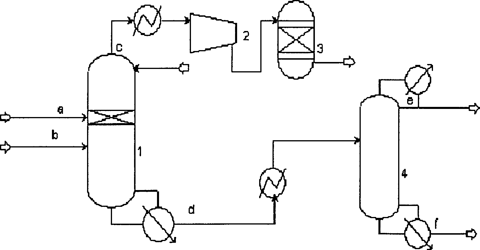
[0063] For a schematic diagram of the process, see figure 2 .
[0064] The high-pressure depropanizer 1 is a 35-layer sieve tray tower, and the low-pressure depropanizer 4 is a 57-layer sieve tray tower. The cracked gas a after compression, alkali washing and drying enters the 14th plate of the high-pressure depropanizer 1, and the liquid hydrocarbon b produced by compressing the cracked gas enters the 20th plate of the high-pressure depropanizer 1, and the reflux liquid returns to the 1st plate, the top of the tower The gas phase stream c includes hydrogen, methane, carbon distillate, carbon three distillate, etc., and the liquid phase stream d in the bottom of the tower includes propane, propylene, propyne, propadiene, C4, C5, C6, benzene, toluene and other components. The stream c is mined and compressed in five stages, and after being compressed by the compressor 2, it enters the gas-phase hydrogenation reactor 3, and the stream d is mined out of the 28th plate of the lo...
Embodiment 2
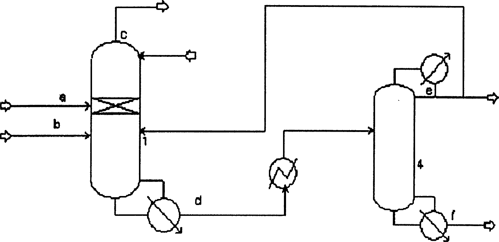
[0069] For a schematic diagram of the process flow, see image 3 .
[0070] The high-pressure depropanizer 1 is a 35-layer sieve tray tower, and the low-pressure depropanizer 4 is a 57-layer sieve tray tower. The cracked gas a enters the 14th plate of the high-pressure depropanizer 1, the liquid hydrocarbon b enters the 20th plate of the high-pressure depropanizer 1, the reflux liquid returns to the 1st plate, the gaseous phase stream c at the top of the tower is extracted and compressed in five stages, and the liquid phase stream in the tower bottom d Mining out of the 28th plate of the low-pressure depropanizer 4. The gas phase stream e (containing C3 and C4 fractions) at the top of the low-pressure depropanizer 4 returns to the 20th plate of the high-pressure depropanizer 1 after condensation except part of the reflux; the liquid phase stream f in the bottom of the tower goes to the debutanizer. The pressure at the top of the high-pressure depropanizer 1 is 1.4 MPa, and t...
Embodiment 3
[0074] For a schematic diagram of the process flow, see image 3 .
[0075] The high-pressure depropanizer 1 is a 35-layer sieve tray tower, and the low-pressure depropanizer 4 is a 57-layer sieve tray tower. The cracked gas a enters the 14th plate of the high-pressure depropanizer 1, the liquid hydrocarbon b enters the 20th plate of the high-pressure depropanizer 1, the reflux liquid returns to the 1st plate, the gaseous phase stream c at the top of the tower is extracted and compressed in five stages, and the liquid phase stream in the tower bottom d Mining out of the 28th plate of the low-pressure depropanizer 4. After condensation, except for reflux, 50% (weight) of the stream returns to the 20th plate of the high-pressure de-propanizer 1, and the rest of the stream goes to the propylene refining tower; Phase stream f goes to the debutanizer. The pressure at the top of the high-pressure depropanizer 1 is 1.4 MPa, and the catalytic reaction temperature is 5-40°C. The pr...
PUM
| Property | Measurement | Unit |
|---|---|---|
| diameter | aaaaa | aaaaa |
| volume ratio | aaaaa | aaaaa |
| volume ratio | aaaaa | aaaaa |
Abstract
Description
Claims
Application Information
 - R&D
- Intellectual Property
- Life Sciences
- Materials
- Tech Scout
- Unparalleled Data Quality
- Higher Quality Content
- 60% Fewer Hallucinations
Browse by: Latest US Patents, China's latest patents, Technical Efficacy Thesaurus, Application Domain, Technology Topic, Popular Technical Reports.
© 2025 PatSnap. All rights reserved.Legal|Privacy policy|Modern Slavery Act Transparency Statement|Sitemap|About US| Contact US: help@patsnap.com