Time-resolved fluorescnet detection method and detector for gene chip
A technology of time-resolved fluorescence and gene chips, which is applied in the detection of gene chips and the field of special detection devices to realize this method, can solve the problems of low sensitivity, narrow analysis range, existence of impurities and noise, etc., and achieve long storage period and wide linear range , good stability
- Summary
- Abstract
- Description
- Claims
- Application Information
AI Technical Summary
Problems solved by technology
Method used
Image
Examples
Embodiment 1
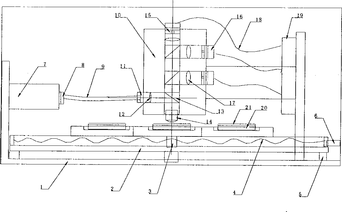
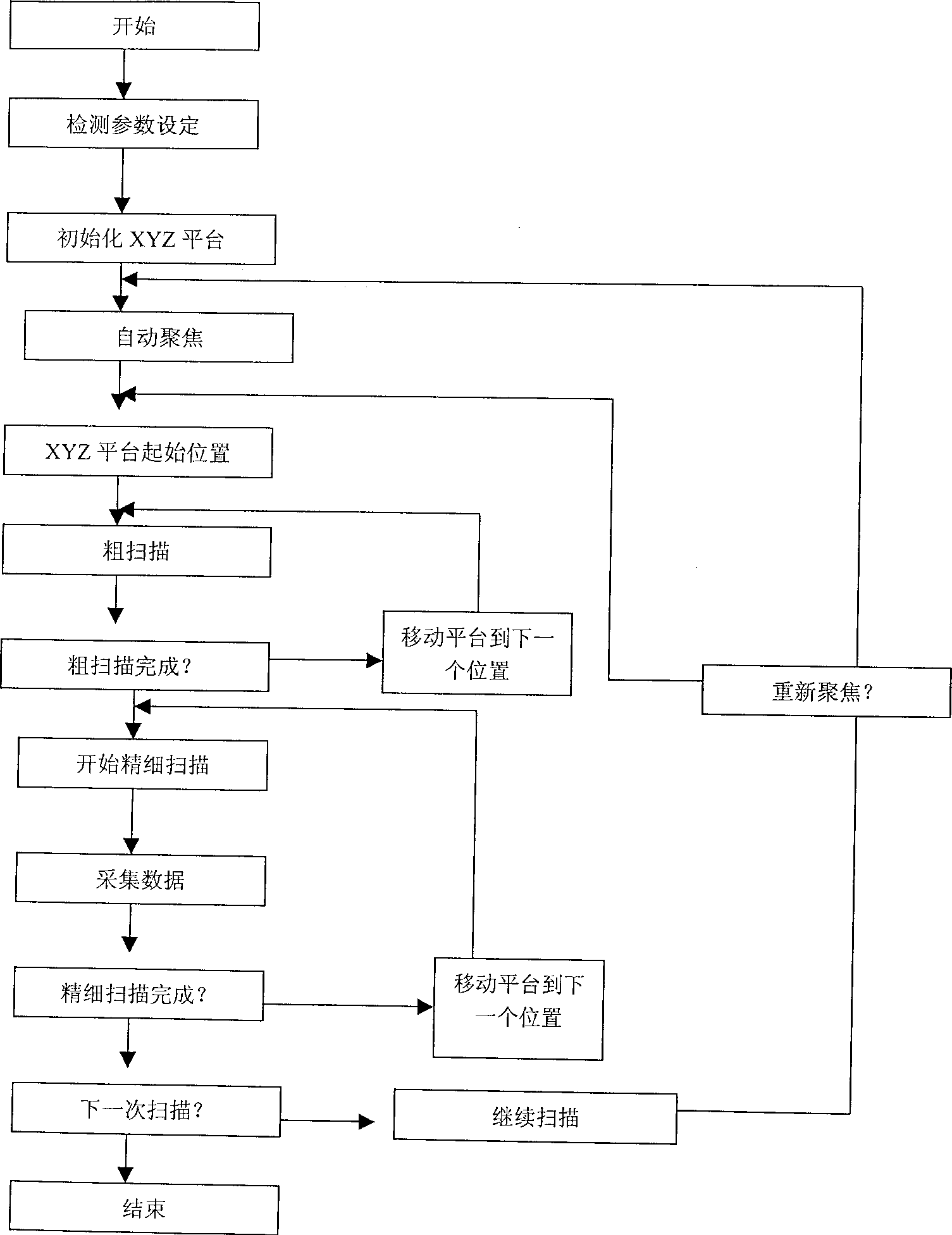
[0020] The steps to realize the gene chip time-resolved fluorescence detection method in this embodiment are: A. Immobilize the DNA probe array on the chip substrate, and mark it with the dye (such as europium, ruthenium ion and other chelates) bound by the rare earth element chelate The target molecule is hybridized in the hybridization box, and then the chip is cleaned, and the cleaned chip is placed on the detection platform; B. A nitrogen molecular laser with a light source wavelength of 337nm is used as the detection light source, and the light pulse width is 10ns after modulation. The light pulse repetition frequency is 15-20Hz, the incident light shines on the hybridization area of the gene chip through the fluorescent lens, the excited dye emits 613nm fluorescence, enters the detection optical path through the lens with a high numerical aperture of 0.8 mm, and the gene chip emits light to the excitation light (337nm) also enters the detection optical path; C. Both the...
Embodiment 2
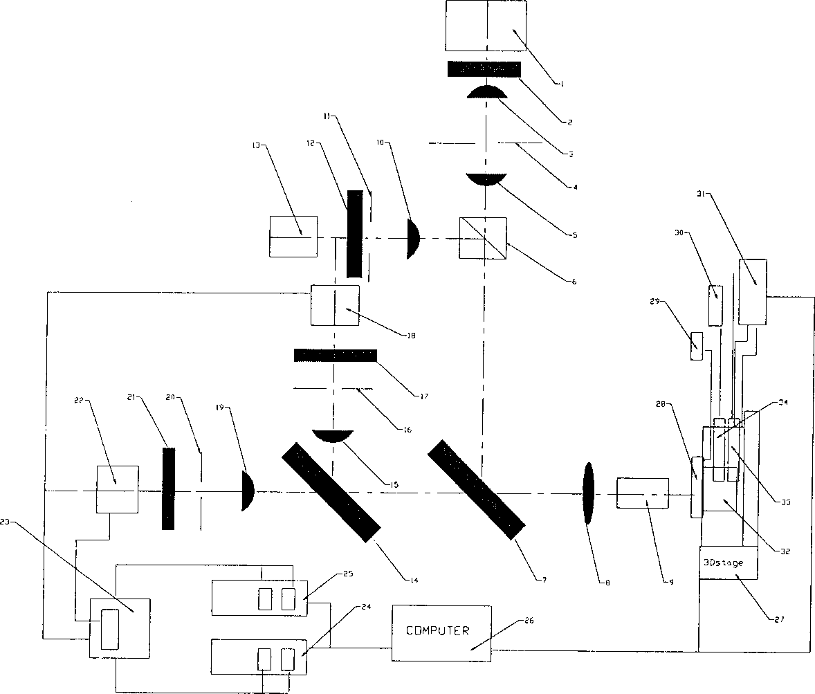
[0026] The steps of the time-resolved fluorescence detection method for the gene chip in this example differ from Example 1 in three main points: the hybridization reaction is carried out on the detector; beam-splitting optical path is used; and the delay time is short. Its concrete steps are as follows: A. DNA probe array is fixed on the chip substrate of spectral transparency with mechanical spotting, spray spot or in-situ synthesis method, and the material of chip adopts the LB film of polymer (also can be functionalized glass , Quartz, Si, Ge, GaAs, GaP, SiO 2 、Si 3 N 4 , modified Si gels, polymers, or gels such as polytetrafluoro, polyaluminum, polycarbonate, polymers, or their mixtures); the shape of the chip is a disc (also can be a square , round and other shapes); the surface of the chip adopts various microfabrication methods to produce the required surface features such as ribs, V-shaped grooves, and micro-holes; the hybridized area is closely connected with the f...
Embodiment 3
[0034] The difference between the present embodiment and the second embodiment is that the acquisition process is delayed by 800 microseconds, and the DNA probe array is first fixed on the spectrally transparent chip substrate, and then hybridized with the target molecule labeled with the rare earth ion chelate dye. Cartridge for hybridization reaction; after cleaning, place the chip on the support platform of the detection device; perform detection according to the steps after Example 1F. The device used is the same as in Example 1. Experiments have proved that the result is feasible.
PUM
 Abstract
Description
Claims
Application Information
 - R&D
- Intellectual Property
- Life Sciences
- Materials
- Tech Scout
- Unparalleled Data Quality
- Higher Quality Content
- 60% Fewer Hallucinations
Browse by: Latest US Patents, China's latest patents, Technical Efficacy Thesaurus, Application Domain, Technology Topic, Popular Technical Reports.
© 2025 PatSnap. All rights reserved.Legal|Privacy policy|Modern Slavery Act Transparency Statement|Sitemap|About US| Contact US: help@patsnap.com


