

Organic/high molecular light emitting diode
A technology of light-emitting diodes and polymers, which is applied to electrical components, circuits, and electrical solid-state devices. It can solve problems such as poor efficiency, and achieve the effects of good long-term stability, excellent electron injection, and excellent air and water vapor stability.
- Summary
- Abstract
- Description
- Claims
- Application Information
AI Technical Summary
Problems solved by technology
Method used
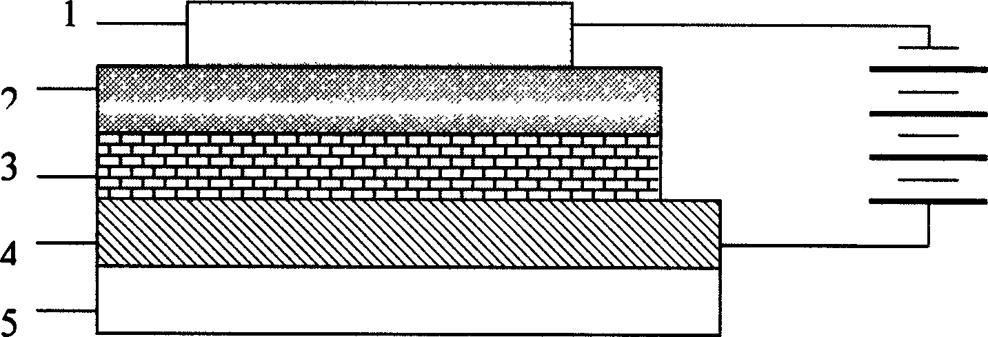
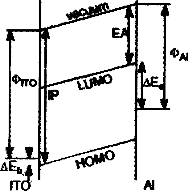
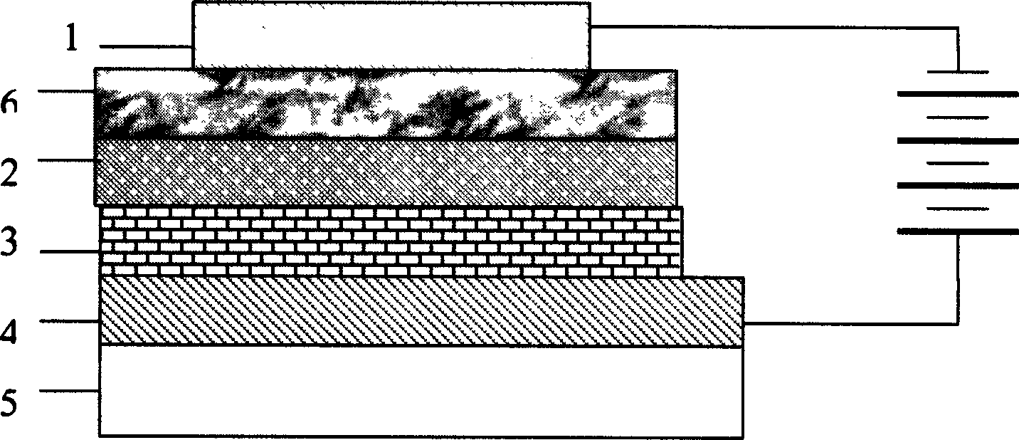
Image

Examples
Embodiment 1
[0034] Embodiment 1: the preparation of 2,7-dibromofluorene
[0035] 2,7-Dibromofluorene was prepared according to the method disclosed in World Patent WO 99 05184 in 1997 and the method disclosed in "Chem. Mater" (Chem. Mater) 11 (1997) 11083. Weigh fluorene (16.6 g, 0.1 mol) and iron powder (88 mg, 1.57 mmol) into a three-necked flask, add 100 ml of chloroform, cool in an ice-water bath, add bromine (35.2 g, 0.22 mol) and 35 milliliters of chloroform, the temperature in the bottle should not exceed 5°C during the dropwise addition. After the reaction was completed, it was filtered and recrystallized with chloroform to obtain white crystals (26.9 g, 83%). 13 C NMR and GC-MASS tests showed that it was the target product 2,7-dibromofluorene.
[0036]
Embodiment 2
[0037] Example 2: Preparation of 2,7-dibromo-9,9-disubstituted fluorene
[0038] The preparation of 2,7-dibromo-9,9-di-n-octylfluorene is taken as an example to illustrate. 2,7-Dibromo-9,9-di-n-octylfluorene was prepared according to the method disclosed in World Patent WO 99 05184 in 1997 and the method disclosed in "Chem. Mater" (Chem. Mater) 11 (1997) 11083. Get 2,7-dibromofluorene (9.72 grams, 0.03 moles) obtained in Example 1, and pour benzyltriethylammonium chloride (0.07 grams, 0.3 mmoles) into a three-necked flask, and add 90 milliliters of dimethyl sulfoxide , 45 ml of 50% aqueous sodium hydroxide solution by weight, stirred vigorously at room temperature to form a suspension, added dropwise 1-bromo-n-octane (12.5 g, 65 mmol), continued to stir for 3 hours, then extracted with ether, combined ether phase, washed with saturated aqueous sodium chloride, and dried over anhydrous magnesium sulfate. The solvent was evaporated, and purified by column chromatography using ...
Embodiment 3
[0041] Embodiment 3: 3, the preparation of 6-dibromocarbazole
[0042] Add carbazole (12.54 grams, 75 mmoles), 375 milliliters of refined carbon disulfide and 24 milliliters of anhydrous pyridine in a 1000 milliliter three-necked flask, stir with a mechanical stirrer while cooling with ice water, when cooled to 0 ° C, start to drop Liquid bromine (28.30 g, 177 mmol) dissolved in 75 ml of carbon disulfide was added dropwise for about 1 hour. After dropping, remove the cooling device, gradually raise to 15°C, keep stirring at 15°C for 2.5 hours, and the reaction ends. The reaction solution was poured into 400 ml of dilute hydrochloric acid, a pale yellow precipitate formed, filtered, washed with dilute sodium hydroxide solution 3 times, then washed with distilled water until neutral, and dried. Recrystallized with absolute ethanol and dried to obtain white needle-like crystals with a yield of 83%. 1 HNMR and GC-MASS tests showed that it was the target product 3,6-dibromocarbaz...
PUM
 Abstract
Description
Claims
Application Information