Method of forming boride coating layer on Ti3 SiC2 material surface
A boride and coating technology, applied in metal material coating process, coating, solid diffusion coating and other directions, can solve the problems of high cost, long operation time, large power consumption, etc., and achieve excellent wear resistance, High surface hardness and practical effect
- Summary
- Abstract
- Description
- Claims
- Application Information
AI Technical Summary
Problems solved by technology
Method used
Image


Examples
Embodiment 1
[0016] The composition of the solid powder mixture of the present invention: boron carbide powder purity ≥ 90%, particle size ≤ 0.4 mm; silicon carbide powder purity ≥ 88.5%, particle size ≤ 0.2 mm; silicon powder purity ≥ 99.00%, particle size ≤ 0.4 mm; potassium fluoroborate is Analytical pure; Sodium fluoride is analytically pure.
[0017] The specific data of this embodiment are: Ti 3 SiC 2 The size of the sample is 5×5×2 mm, and the composition of the powder mixture is by weight percentage: 64% boron carbide, 32% silicon carbide, 1% silicon, 2% potassium fluoroborate, 1% sodium fluoride, and the total weight is 100g. Fill it with argon (99.99% Ar), the heating temperature is 1300°C, the heating rate is 8°C / min, the holding time is 8 hours, and the sample is taken out after the furnace is cooled to room temperature.
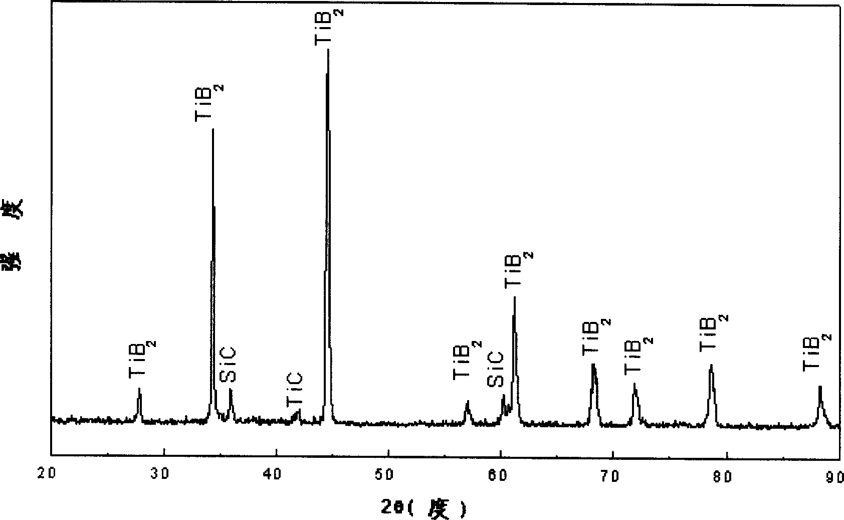
[0018] X-ray diffraction analysis shows that after the above process, Ti 3 SiC 2 A titanium diboride coating is mainly formed on the surface of the mater...
Embodiment 2
[0020] The difference from Example 1 is: Ti 3 SiC 2 The material sample is 5×5×2 mm, and the composition of the powder mixture is by weight percentage: 45% boron carbide, 50% silicon carbide, 2% silicon, 2% potassium fluoroborate, 1% sodium fluoride, and the total weight is 100g. Fill it with helium (99.99% He), the heating temperature is 1400°C; the heating rate is 6°C / min, and the holding time is 6 hours. The samples were taken out after the furnace was cooled to room temperature.
[0021] Tested at Ti 3 SiC 2 A titanium diboride coating about 36 microns thick is formed on the surface of the material sample. By measuring the mass change of the sample after infiltration, the amount of infiltration is 2.75mg / cm 2 . The surface Vickers hardness is about 24GPa. The surface of the infiltrated sample is smooth and off-white. Observation of the cross-section shows that the coating is continuous and complete, and well combined with the substrate.
Embodiment 3
[0023] The difference from Example 1 is: Ti 3 SiC 2 The material sample is 5×5×2 mm, and the composition of the powder mixture is by weight percentage: 50% boron carbide, 46% silicon carbide, 1% silicon, 2% potassium fluoroborate, 1% sodium fluoride, and the total weight is 100g. The heating temperature is 1100°C; the heating rate is 6°C / min, and the holding time is 10 hours. The samples were taken out after the furnace was cooled to room temperature.
[0024] Tested at Ti 3 SiC 2 A titanium diboride coating about 5 microns thick is formed on the surface of the material sample. By measuring the mass change of the sample after infiltration, the amount of infiltration is 0.35mg / cm 2 . The surface Vickers hardness is about 22GPa. The surface of the infiltrated sample is smooth and silvery white. Cross-section observation, due to the Ti 3 SiC 2 The material contains impurity phase SiC, the coating is not covered in SiC, and the rest is well combined with the substrate.
PUM
| Property | Measurement | Unit |
|---|---|---|
| Surface vickers hardness | aaaaa | aaaaa |
Abstract
Description
Claims
Application Information
 - Generate Ideas
- Intellectual Property
- Life Sciences
- Materials
- Tech Scout
- Unparalleled Data Quality
- Higher Quality Content
- 60% Fewer Hallucinations
Browse by: Latest US Patents, China's latest patents, Technical Efficacy Thesaurus, Application Domain, Technology Topic, Popular Technical Reports.
© 2025 PatSnap. All rights reserved.Legal|Privacy policy|Modern Slavery Act Transparency Statement|Sitemap|About US| Contact US: help@patsnap.com