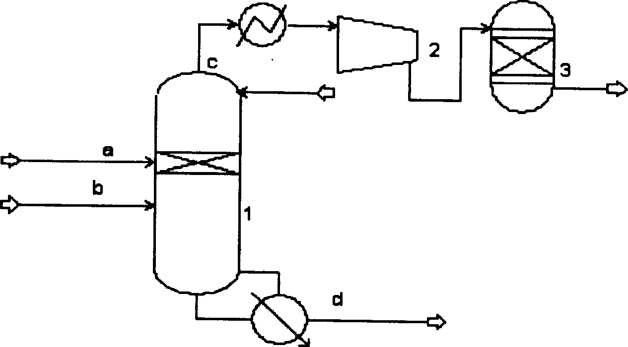
Catalytic distillation process for olefin production device
A production device and catalytic rectification technology, which is applied in the field of catalytic rectification and selective hydrogenation of carbon 2 and carbon 3 highly unsaturated hydrocarbon components, which can solve problems such as low utilization rate, uneven liquid distribution, and complicated separation system process
- Summary
- Abstract
- Description
- Claims
- Application Information
AI Technical Summary
Problems solved by technology
Method used
Image
Examples
Embodiment 1
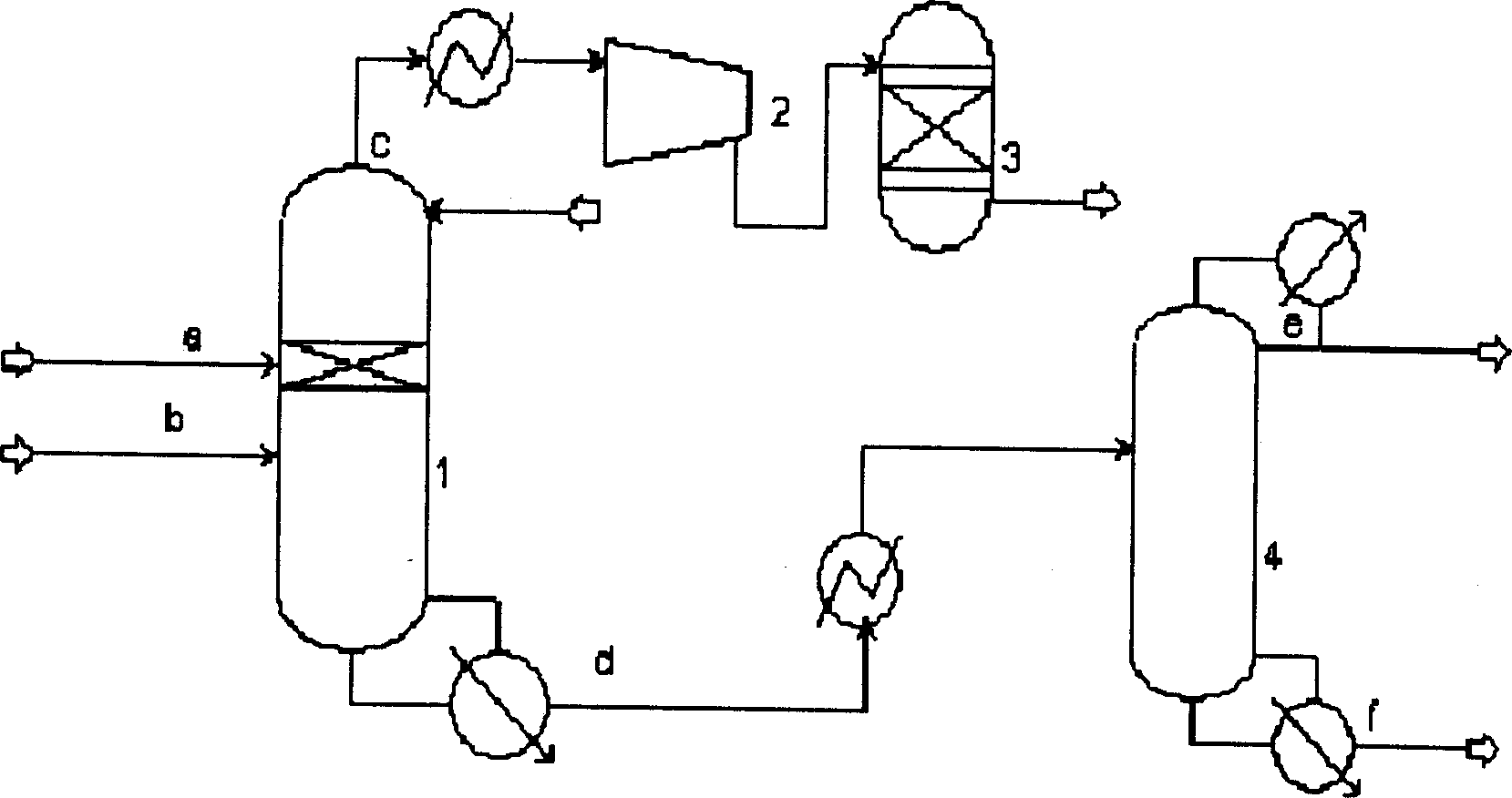
[0063] For a schematic diagram of the process, see figure 2 .
[0064] The high-pressure depropanizer 1 is a 35-layer sieve tray tower, and the low-pressure depropanizer 4 is a 57-layer sieve tray tower. The cracked gas a after compression, alkali washing and drying enters the 14th plate of the high-pressure depropanizer 1, and the liquid hydrocarbon b produced by compressing the cracked gas enters the 20th plate of the high-pressure depropanizer 1, and the reflux liquid returns to the 1st plate, the top of the tower The gas phase stream c includes hydrogen, methane, carbon distillate, carbon third distillate, etc., and the liquid phase stream d in the bottom of the tower includes propane, propylene, propyne, propadiene, C4, C5, C6, benzene, toluene and other components. The stream c is mined and compressed in five stages, and after being compressed by the compressor 2, it enters the gas-phase hydrogenation reactor 3, and the stream d is mined out of the 28th plate of the lo...
Embodiment 2
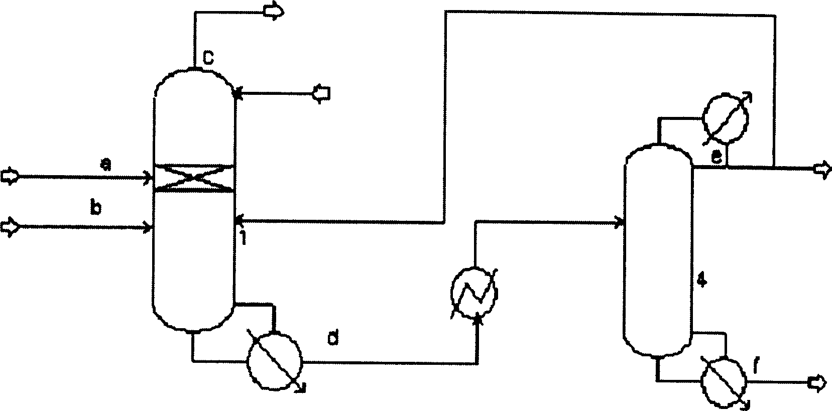
[0069] For a schematic diagram of the process flow, see image 3 .
[0070] The high-pressure depropanizer 1 is a 35-layer sieve tray tower, and the low-pressure depropanizer 4 is a 57-layer sieve tray tower. The cracked gas a enters the 14th plate of the high-pressure depropanizer 1, the liquid hydrocarbon b enters the 20th plate of the high-pressure depropanizer 1, the reflux liquid returns to the 1st plate, the gaseous phase stream c at the top of the tower is extracted and compressed in five stages, and the liquid phase stream in the tower bottom d Mining out of the 28th plate of the low-pressure depropanizer 4. After condensation, the overhead gaseous stream e (containing C3 and C4 fractions) of the low-pressure depropanizer 4 returns to the 20th plate of the high-pressure depropanizer 1 except for part of the reflux; the liquid phase stream f in the bottom of the tower goes to the debutanizer. The pressure at the top of the high-pressure depropanizer 1 is 1.4 MPa, and ...
Embodiment 3
[0074] For a schematic diagram of the process flow, see image 3 .
[0075] The high-pressure depropanizer 1 is a 35-layer sieve tray tower, and the low-pressure depropanizer 4 is a 57-layer sieve tray tower. The cracked gas a enters the 14th plate of the high-pressure depropanizer 1, the liquid hydrocarbon b enters the 20th plate of the high-pressure depropanizer 1, the reflux liquid returns to the 1st plate, the gaseous phase stream c at the top of the tower is extracted and compressed in five stages, and the liquid phase stream in the tower bottom d Mining out of the 28th plate of the low-pressure depropanizer 4. After the low-pressure depropanizer 4 overhead gas phase stream e (containing C3, C4 cuts) is condensed, except for reflux, 50% (weight) of the stream returns to the 20th plate of the high-pressure de-propanizer 1, and the rest of the stream goes to the propylene refining tower; The liquid phase stream f goes to the debutanizer. The pressure at the top of the hi...
PUM
| Property | Measurement | Unit |
|---|---|---|
| diameter | aaaaa | aaaaa |
| volume ratio | aaaaa | aaaaa |
| volume ratio | aaaaa | aaaaa |
Abstract
Description
Claims
Application Information
 - R&D
- Intellectual Property
- Life Sciences
- Materials
- Tech Scout
- Unparalleled Data Quality
- Higher Quality Content
- 60% Fewer Hallucinations
Browse by: Latest US Patents, China's latest patents, Technical Efficacy Thesaurus, Application Domain, Technology Topic, Popular Technical Reports.
© 2025 PatSnap. All rights reserved.Legal|Privacy policy|Modern Slavery Act Transparency Statement|Sitemap|About US| Contact US: help@patsnap.com


