Colour optical filter

A color filter and dice technology, applied in the field of color filters, can solve the problems of poor heat resistance, low light transmittance and contrast, and achieve good heat resistance, high light transmittance and contrast Effect

Inactive Publication Date: 2006-06-14
HONG FU JIN PRECISION IND (SHENZHEN) CO LTD +1
View PDF0 Cites 20 Cited by
  • Summary
  • Abstract
  • Description
  • Claims
  • Application Information

AI Technical Summary

Problems solved by technology

[0004] In order to overcome the disadvantages of poor heat resistance, low light transmittance and low contrast of the prior a...

Method used


Image

  • Colour optical filter
  • Colour optical filter

Examples


Embodiment Construction

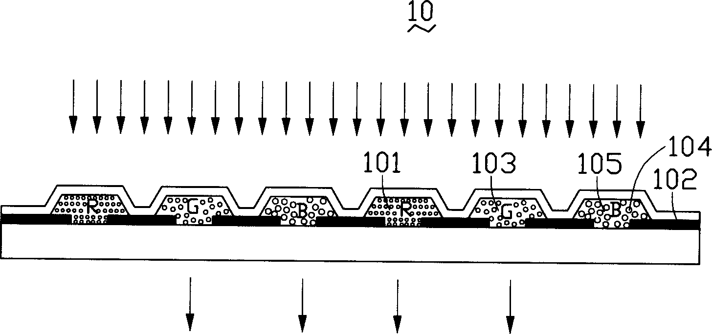
[0009] see figure 1 , is a structural schematic diagram of the color filter of the present invention. The color filter 10 mainly includes a plurality of pixels, each pixel includes sub-pixels 101, 103, and 105 of red, green, and blue colors, and a black matrix 102 is arranged between each sub-pixel to block the to prevent light leakage and prevent mixing of photoresist materials, the red, green and blue sub-pixels 101, 103, 105 include a particle size of 1×10 -9 ~1×10 -7 M. Nanoparticles 104 . The nanoparticles 104 may be one or a combination of aluminum, titanium, chromium, nickel, silver, zinc, molybdenum, tantalum, tungsten, palladium, copper, gold, and platinum. Because when a substance exists at a nanometer size, its electrical conductivity, magnetism, electrical resistance, physical and chemical properties all change dramatically. As far as metals are concerned, due to the quantum confinement effect, when the number of atoms of the particle is reduced to a certain ex...


PUM


Abstract

The invention discloses a color screen that contains plural pixels, each of which includes red, green, and blue sub-pixels. The sub-pixels contain nm particles that could control the transmitted spectrum range of each sub-pixel. The diameter of the particle is 1x10⁻⁹-1x10⁻⁷meter. It could be metal, semiconductor, or semiconductor compound. The particle would improve the thermal endurance, light transmission rate and contrast of color screen.

Description

【Technical field】 [0001] The invention relates to a color filter, in particular to a color filter used in a liquid crystal display device. 【Background technique】 [0002] Liquid crystal display is a passive display device. In order to achieve the effect of color display, it is necessary to provide a color filter. Its function is to convert the passing white light into three primary color beams of red, green and blue. Layers and other components such as liquid crystals in between to achieve the effect of displaying different color images. The color filter is generally placed between the upper substrate and the Indium Tin Oxide (ITO) electrode, and mainly includes a black matrix and a coloring layer. [0003] At present, the manufacturing method of the color filter basically adopts the pigment dispersion method, and the color photoresist is coated on the substrate in the manner of spin coating, and then exposed and developed to form lithographic color blocks. Most of the col...

Claims


Application Information

Patent Timeline
IPC IPC(8): G02B5/23G02F1/1335
Inventor 吴美玲
Owner HONG FU JIN PRECISION IND (SHENZHEN) CO LTD
Why Eureka
Try Eureka