

Direct spraying method for preparing fuel cell membrane electrode
A fuel cell membrane, direct technology, applied in fuel cell parts, battery electrodes, devices for coating liquid on the surface, etc. High output energy density, no swelling and deformation, and the effect of simplifying the preparation process
- Summary
- Abstract
- Description
- Claims
- Application Information
AI Technical Summary
Problems solved by technology
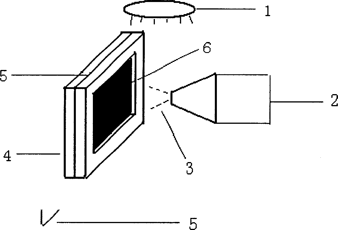
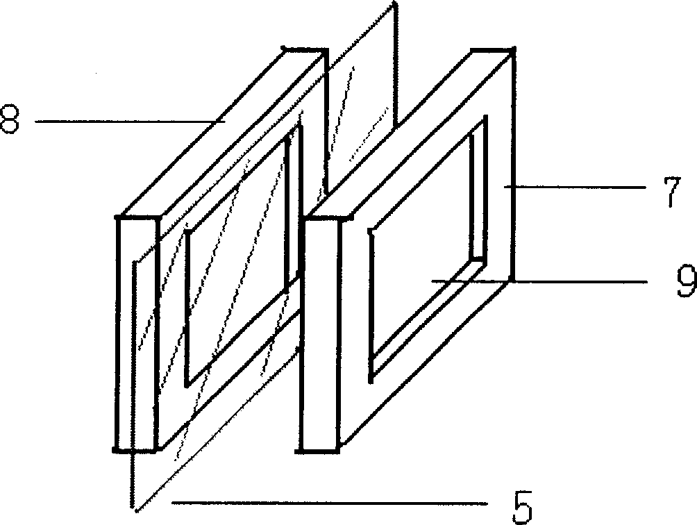
Method used
Image

Examples
Embodiment 1
[0042] (1) Proton exchange membrane pretreatment
[0043] Put a piece of 4cm×4cm Nafionl 12 film in 3-5% by weight hydrogen peroxide solution, treat it at 80°C for 1 hour, wash it with double distilled water, and place it in 0.5mol / L at 80°C Sulfuric acid solution was processed, then washed with double distilled water, and fixed with a membrane (the area of the middle part was 5cm 2 ) were fixed and dried under vacuum at 60°C for 2 hours.
[0044] (2) Preparation of cathode catalyst slurry
[0045] Weigh 14mg of Pt / C catalyst (Pt content is 20% by weight) and place it in a vial, first add 10mg of deionized water, then add 100mg of 5% by weight Nafion solution and 1ml of isopropanol, and ultrasonically disperse for 30 minutes to prepare a cathode catalyst slurry material.
[0046] (3) Preparation of anode catalyst slurry
[0047] Weigh 14mg of Pt / CNT catalyst (Pt content is 20% by weight) and place in a vial, first add 10mg of deionized water, then add 100mg of 5% by weig...
Embodiment 2
[0053] (1) The selected proton exchange membrane and proton exchange membrane pretreatment thereof are the same as in Example 1.
[0054] (2) Preparation of cathode catalyst slurry
[0055] (2) Preparation of cathode catalyst slurry
[0056] Take by weighing 14mg Pt / C catalyst (Pt content is 20% by weight) and place in vial, first add 10mg deionized water, then add 100mg 5% by weight Nafion solution, 50mg 6.6% by weight Teflon emulsion, and 1ml isopropanol, The cathode catalyst slurry was prepared by ultrasonic dispersion for 30 minutes.
[0057] (3) Preparation of anode catalyst slurry
[0058] Take by weighing 7mg Pt / CNT catalyst (Pt content is 33% by weight) and place in vial, add 10mg deionized water earlier, then add 142mg 5% by weight Nafion solution (containing nafion 7mg), the Teflo emulsion of 50mg 6.6% by weight, and 1.5ml of isopropanol, ultrasonically dispersed for 30 minutes to prepare the anode catalyst slurry.
[0059] (4) Preparation of membrane electrodes ...
Embodiment 3
[0063] (1) The selected proton exchange membrane and the pretreatment of the proton exchange membrane are the same as in Example 1.
[0064] (2) Preparation of cathode catalyst slurry
[0065] Weigh 20mg of Pt / C catalyst (Pt content is 20% by weight) and place it in a vial, first add 5mg of double distilled water, then add 142mg of 5% by weight Nafion solution, and 3ml of isopropanol, and ultrasonically disperse for 30 minutes.
[0066] (3) Preparation of anode catalyst slurry
[0067] Weigh 20mg of Pt / CNT catalyst (Pt content is 20% by weight) and place it in a vial, first add 0.05ml of double distilled water, then add 142mg of 5% by weight Nafion solution, and 3ml of isopropanol, and ultrasonically disperse for 30 minutes.
[0068] (4) Preparation of membrane electrodes
[0069] The spraying and drying method of the catalyst layer are the same as in Example 1. During the preparation process, no swelling and deformation of the membrane occurred. A membrane electrode with ...
PUM
| Property | Measurement | Unit |
|---|---|---|
| thickness | aaaaa | aaaaa |
Abstract
Description
Claims
Application Information