Ultra low reflectivity hydrophobic coating and method therefor

a hydrophobic coating and ultra-low reflectivity technology, applied in the field of ultra-low reflectivity hydrophobic coatings, can solve the problems of faulty or lowering the performance beyond an acceptable threshold, prone to attack, and difficult to reproduce the best performance of aligned carbon nanostructure coatings with any consistency on commercial substrates, so as to reduce the reflectance

Active Publication Date: 2018-10-30
SURREY NANOSYST
View PDF10 Cites 2 Cited by
  • Summary
  • Abstract
  • Description
  • Claims
  • Application Information

AI Technical Summary

Benefits of technology

[0020]The teachings of the preferred embodiments described herein are directed to the deposition and functionalization by a plasma fluoropolymer onto a carbon nanotube array in order to improve hydrophobicity whilst simultaneously improving optical absorption characteristics in the electromagnetic spectrum.
[0022]The disclosed method of making the carbon nanostructure layer hydrophobic and lowering the surface energy can also significantly improve the film's absorption across the electromagnetic spectrum due to the tip clustering produced during exposure to the plasma.
[0023]The inventors have discovered that the hydrophobic coating and etch process taught herein, surprisingly, improves the film's reflectivity by the same as an oxygen only process.
[0024]In the preferred embodiment, the hydrophobic material coating is discontinuous across the layer of carbon nanostructures and preferably also extends at least partially through a thickness of the carbon nanostructure layer. The coating does not have to be a continuous film as long as the nanostructure tips are coated as the tip density and high contact angle will result in a lack of capillary action thereby restricting water ingress. In a practical embodiment, the hydrophobic coating extends to at least 3 micrometers along the lengths of the nanostructures without forming a continuous over-layer, but the surface energy modification can substantially extend the full length of the carbon nanostructure. In some embodiments, the coating may thus extend for the full length of the nanostructures.
[0033]The fluorocarbon or organosilane coating lowers the surface energy of the exposed surface of the carbon nanostructure layer, thereby causing the layer to be hydrophobic.
[0037]The hydrophobic material preferably is or includes a fluoropolymer. In a practical embodiment, the hydrophobic material includes carbon tetrafluoride as a precursor. The precursor may be used by itself but in other embodiments, the carbon tetrafluoride precursor is provided with a hydrocarbon reactant, advantageously of acetylene. In a practical embodiment, the carbon tetrafluoride and acetylene are provided at a ratio of substantially 90% to 10%, respectively. In a practical embodiment, the plasma is generated at about 100 degrees Centigrade by means of RF energy at a frequency of 13.56 MHz. The RF energy is delivered to an electrode in a way typically used in PECVD reactors. Suitable RF powers, electrode spacing and process pressures can be used to minimise precursor fragmentation. Advantageously, the plasma is formed at a pressure of around 1.2 Torr.

Problems solved by technology

Any contamination from such coatings will inevitably collect or condense on the detectors rendering them faulty or lowering their performance beyond an acceptable threshold.
When grown at a commercial scale it has proven difficult to reproduce the best performance from aligned carbon nanostructure coatings with any consistency on commercial substrates.
Aligned carbon nanotubes and filaments have been shown to be highly efficient absorbers of electromagnetic energy, and also satisfy many of the key requirements for super-black optical absorbers listed above, but they are prone to attack by atmospheric moisture and humidity.
This is caused by growth defects in the carbon nanostructures, which become more pronounced as their synthesis temperature drops below 900° C. As most super-black coatings made from carbon nanotubes are required to be used on sensitive instrumentation, they tend to be grown at the lowest possible temperature that is compatible with the substrate.
The chemical vapour deposition (CVD) methods used to grow these coatings tend to result in them being very hydrophilic, as growth defects in the tube walls terminate to form highly polar hydroxyl, carbonyl and carboxyl functional groups on exposure to air or trace oxygen.
This hydrophilicity rapidly causes the film to lose its optical properties on exposure to atmospheric humidity or free water, as the film loses its intended highly-absorbing structure and acts like a sponge.
However, coatings made from carbon nanostructures that have been treated with an oxygen or other inert gas plasma are highly defective due to ion damage of the nanostructure shells.
This leads to the nanostructure coating becoming more hydrophilic so, again, when the absorber coating is exposed to atmospheric humidity or water, severe, full length, CNT tube agglomeration rapidly occurs as the moisture is attracted to the highly polar tube defect sites.
This in-turn radically decreases the coating's ability to act as an absorber, making the film unsuitable for practical applications.
Whilst conventional hydrophobic coatings would protect the nanotube coating from water and humidity, they also drastically reduce the combined polymer / absorber film's absorbing properties by changing the film's refractive index, blocking the existing optical trapping cavities and reducing the photon absorption efficiency of the individual nanotubes or filaments.
Most polymers are insulators, which means that their band gap is too large for an electron to be excited easily by a photon.
When a CNT is over coated in polymer material it makes this absorption far less efficient, resulting in far higher reflectance from the coating.
To date, these issues have not been addressed or resolved in aligned, carbon nanotube or filament electromagnetic (EM) absorber coatings.

Method used


Image

  • Ultra low reflectivity hydrophobic coating and method therefor
  • Ultra low reflectivity hydrophobic coating and method therefor
  • Ultra low reflectivity hydrophobic coating and method therefor

Examples


example 1

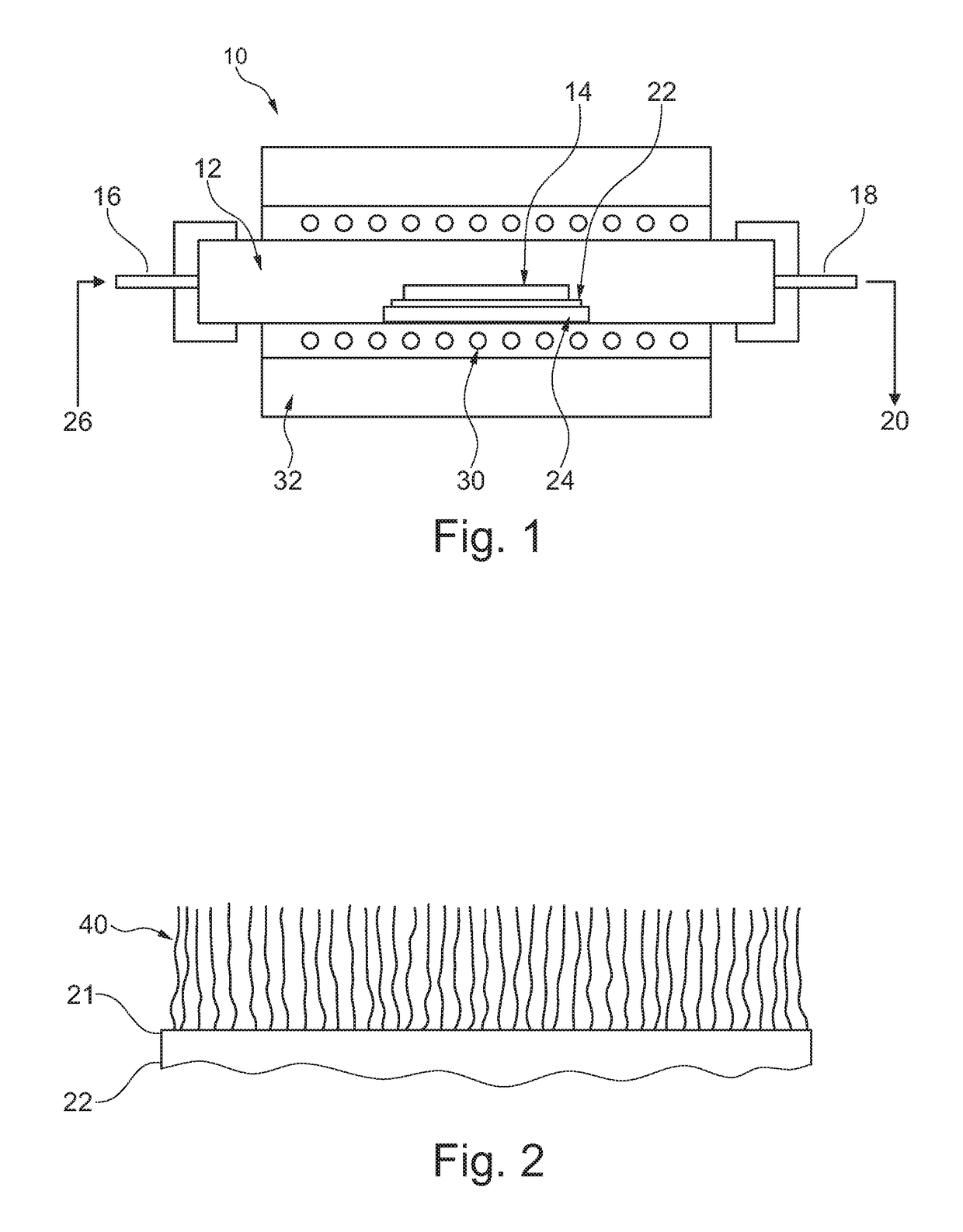
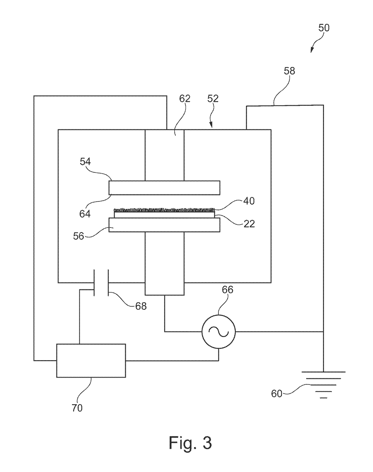
[0108]Plasma deposition was conducted with a 13.56 MHz RF generator and gases were delivered via a shower head delivery system of the type disclosed and referred to above. The carbon nanotube sample was placed in the reactor and evacuated, the sample was allowed to come to temperature at 100° C. for 10 min. In one instance, CF4 (90 sccm) and C2H2 (10 sccm) were flowed into the reactor and the pressure was allowed to stabilise at 1.2 Torr. The plasma was ignited at 30 W and the reaction was allowed to proceed for between 5 and 20 seconds. The resultant sample was removed from the chamber and stored at room temperature in air for subsequent analyses.

[0109]Referring now to FIG. 8, this shows a graph of the expected coating parameters achieved by the apparatus 50 / 100 disclosed herein. Where the process has an initial step of forming an oxygen plasma to cluster, or cause to agglomerate, the free ends of the carbon nanotubes, it has been found that the optimum period for the oxygen plasma...

example 3 (

CF4-C2H2 Plasma—12 s)

[0114]A previously grown CNT forest on an aluminium coupon was loaded into a plasma chamber. The chamber is pumped down to between 10−2 and 10−3 Torr using a rotary vane pump or similar. The plasma conditions used are CF4(90)-C2H2(10), 1.2 Torr, 100° C., 30 W (0.07 W cm−2) and the plasma was sustained for 12 seconds. The sample was removed and its reflectance measured. A 25-35% drop in reflectance was observed across the spectrum as with the O2 etched sample. The sample's resistance to a drop of ultra-pure water being placed on it was assessed and it was seen to behave in a super hydrophobic manner with no wetting possible and the drops rolled away. A comparison of the two samples can be seen in FIGS. 11 and 12.

example 7

ma—300 s)

[0118]A previously grown CNT forest on aluminium foil was loaded into a plasma chamber. The chamber is pumped down to between 10−2 and 10−3 Torr using a rotary vane pump or similar. The plasma conditions used were CF4 1.2 Torr, 300° C., 30 W (0.07 Wcm−2) and the plasma was sustained for 300 seconds. The reflectance of the sample was reduced by 25-35% across the range. Following this treatment, the sample demonstrated super hydrophobic properties as evidenced in FIG. 17 and was stable over a period of several months. The improved stability is attributed to both the increased time of exposure to CFx radicals and the increased temperature.


PUM

PropertyMeasurementUnit
diameteraaaaaaaaaa
lengthaaaaaaaaaa
frequencyaaaaaaaaaa

Abstract

A low reflectivity coating (40, 80 / 82) is provided on a substrate (22). The coating includes a layer of substantially vertically aligned carbon nanotubes (40) on an exposed surface (21) of the substrate. Provided on and extending partially within the carbon nanotube layer (40) is a hydrophobic coating (80, 82), in the preferred embodiment of or containing fluorocarbon. The hydrophobic coating (80, 82) prevents any settling or ingress of water particles onto or into the carbon nanotube layer (40) and as a result increases the stability of the carbon nanotube layer during use (40) while improving the low reflectivity of the film.

Description

CROSS-REFERENCE TO RELATED APPLICATIONS[0001]This application is a § 371 national phase of International Application No. PCT / GB2016 / 052675, filed on Aug. 26, 2016, which claims the benefit of United Kingdom Patent Application No. 1515271.3, filed on Aug. 27, 2015, and United Kingdom Patent Application No. 1516424.7, filed on Sep. 16, 2015, which applications are incorporated by reference herein.TECHNICAL FIELD[0002]The present invention relates to a method of forming a low reflectivity hydrophobic coating on a substrate.BACKGROUND OF THE INVENTION[0003]For a very long time there have been efforts to produce environmentally stable coatings and devices having very low reflectivity for a variety of industrial and scientific applications. These are important in imaging systems, calibration targets, instrumentation, light guides, baffles, stray light suppression and in many other uses.[0004]To be commercially useful, these coatings must have the lowest reflectance possible and be capable...

Claims


Application Information

Patent Timeline
Patent Type & Authority Patents(United States)
IPC IPC(8): B05D1/00C23C16/02C23C16/505B05D5/08B05D3/14
CPCB05D1/62B05D3/142C23C16/505C23C16/0245B05D5/083B05D5/08B05D1/00
Inventor MCKENNA, FIONA-MAIREADHOWLETT, GUY ALEXANDERJENSEN, BEN POUL
Owner SURREY NANOSYST
Why Eureka
Try Eureka