
Negative electrode active material, mixed negative electrode active material, and method of producing negative electrode active material

a technology of active materials and negative electrodes, which is applied in the direction of cell components, electrochemical generators, silicates, etc., can solve the problems of electrolyte consumption, and achieve the effects of favorable cycle performance and initial charge and discharge properties, excellent slurry stability in electrode production, and high capacity

Active Publication Date: 2022-05-17
SHIN ETSU CHEM IND CO LTD
View PDF36 Cites 0 Cited by
  • Summary
  • Abstract
  • Description
  • Claims
  • Application Information

AI Technical Summary

Benefits of technology

[0070]The inventive negative electrode active material brings high capacity and favorable cycle performance and initial charge and discharge property when it is used as a negative electrode active material for a secondary battery. A mixed negative electrode active material containing this negative electrode active material also brings the same effects. The inventive negative electrode active material and mixed negative electrode active material are excellent in slurry stability in production of an electrode.
[0071]The inventive method of producing a negative electrode active material successfully stabilizes the slurry in production of an electrode, making it possible to produce a negative electrode active material that has high capacity as well as favorable cycle performance and initial charge and discharge property when it is used as a negative electrode active material for a secondary battery.

Problems solved by technology

The new surface then causes the decomposition reaction of an electrolyte and is coated with a decomposition product of the electrolyte, thereby consuming the electrolyte.

Method used


Image

  • Negative electrode active material, mixed negative electrode active material, and method of producing negative electrode active material
  • Negative electrode active material, mixed negative electrode active material, and method of producing negative electrode active material
  • Negative electrode active material, mixed negative electrode active material, and method of producing negative electrode active material

Examples


example 1-1

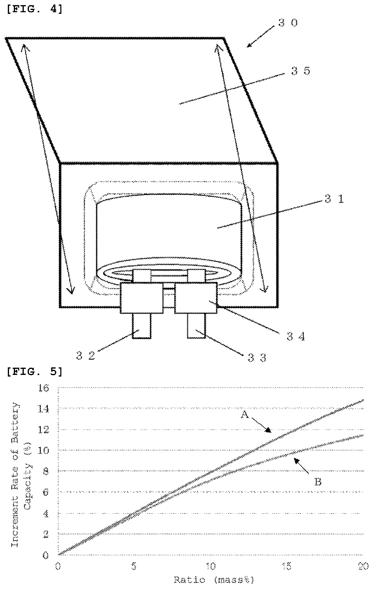
[0190]The laminate film lithium-ion secondary battery 30 shown in FIG. 4 was produced by the following procedure.

[0191]The procedure began with the production of a positive electrode. A positive-electrode mixture was prepared by mixing 95 mass % of LiNi0.7Co0.25Al0.05O of lithium-nickel-cobalt complex oxide (lithium-nickel-cobalt-aluminum complex oxide: NCA) as a positive electrode active material, 2.5 mass % of a positive electrode conductive assistant agent, and 2.5 mass % of a positive electrode binder (polyvinylidene fluoride: PVDF). The positive-electrode mixture was dispersed in an organic solvent (N-methyl-2-pyrrolidone, NMP) to form paste slurry. The slurry was applied to both surfaces of a positive electrode current collector with a coating apparatus having a die head and dried with a drying apparatus of hot-air type. The positive electrode current collector used herein had a thickness of 15 μm. The resultant was finally compressed with a roll press.

[0192]Next, a negative e...

examples 1-2 to 1-5

[0204]A secondary battery was produced as in Example 1-1 except for adjusting the oxygen amount in the bulk of the silicon compound. In this case, the oxygen amount was adjusted by changing the ratio of metallic silicon and silicon oxide in the raw material of silicon compound or heating temperature. Each “x” value of the silicon compound shown by SiOx in Examples 1-1 to 1-5 is shown in Table 1.

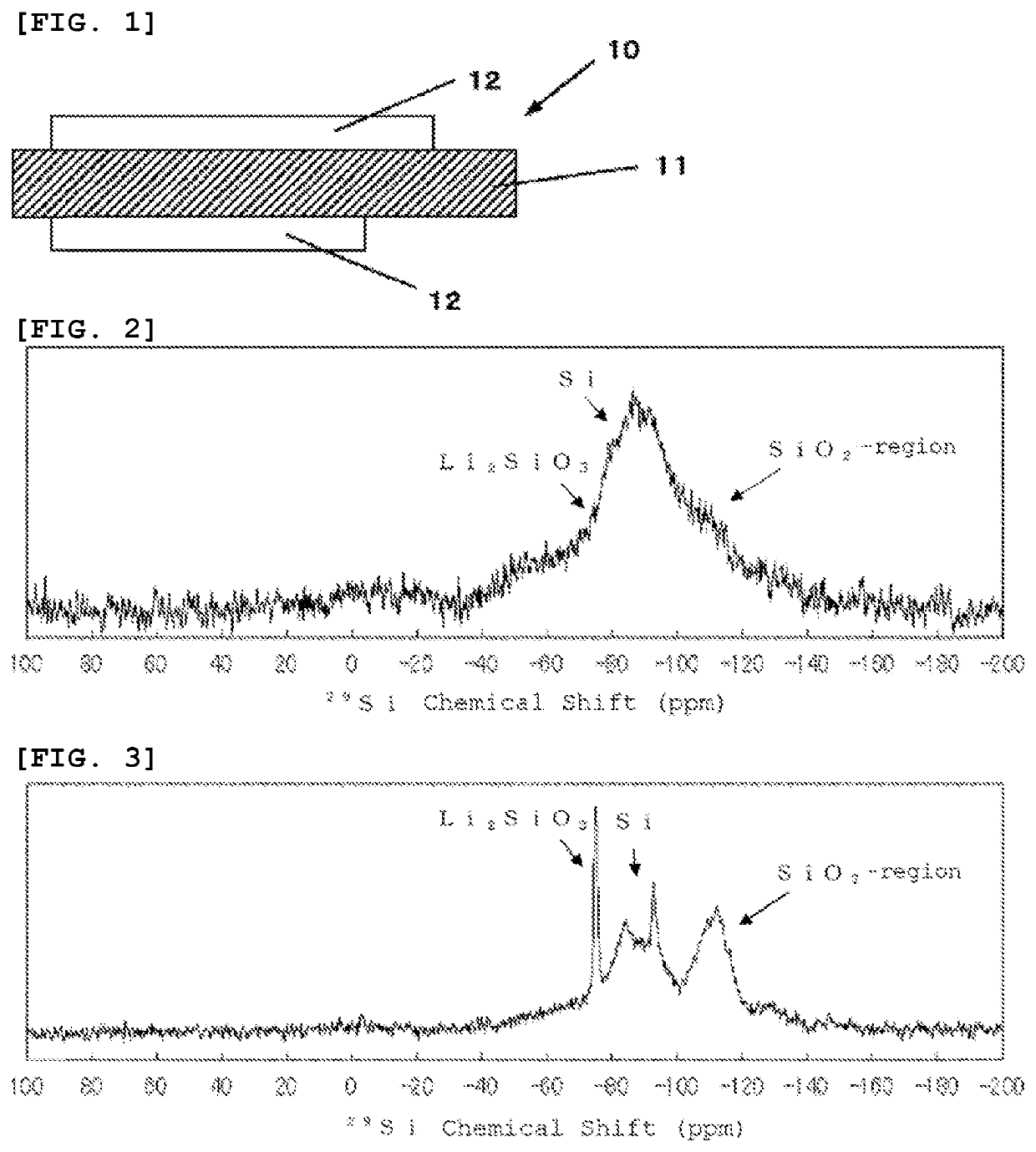
[0205]In this case, the negative electrode active material particles in Examples 1-1 to 1-5 had properties as described below. In the interior of silicon compound particles in the negative electrode active material particles, Li2SiO3 and Li2Si2O5 were contained. The silicon compound had a diffraction peak attributable to Si(111) crystal face in an X-ray diffraction, the half value width (2θ) of which was 2.257°, and the crystallite corresponding to the Si(111) crystal face with the size being 3.77 nm.

[0206]In each of the Examples described above, the 29Si-MAS-NMR spectrum exhibited a peak att...

examples 2-1 to 2-3

[0212]A secondary battery was produced under the same conditions as in Example 1-3 except for changing the kind of lithium silicate contained in the interior of the silicon compound particle as shown in Table 2, and the cycle performance and first efficiency were evaluated. Incidentally, in Example 2-2, the kind of lithium silicate contained in the interior of the silicon compound particle was changed as described in Table 2 by changing the modification method to an oxidation and reduction method.

[0213]That is, in Example 2-2, the silicon compound particle coated with carbon material was modified by oxidation and reduction method to insert lithium. In this case, the negative electrode active material particles containing silicon compound particles were firstly immersed into a solution (solution-A) in which lithium pieces and naphthalene of aromatic compound had been dissolved into tetrahydrofuran (hereinafter referred to as THF). This solution-A was prepared by dissolving naphthalen...


PUM

PropertyMeasurementUnit
binding energyaaaaaaaaaa

Abstract

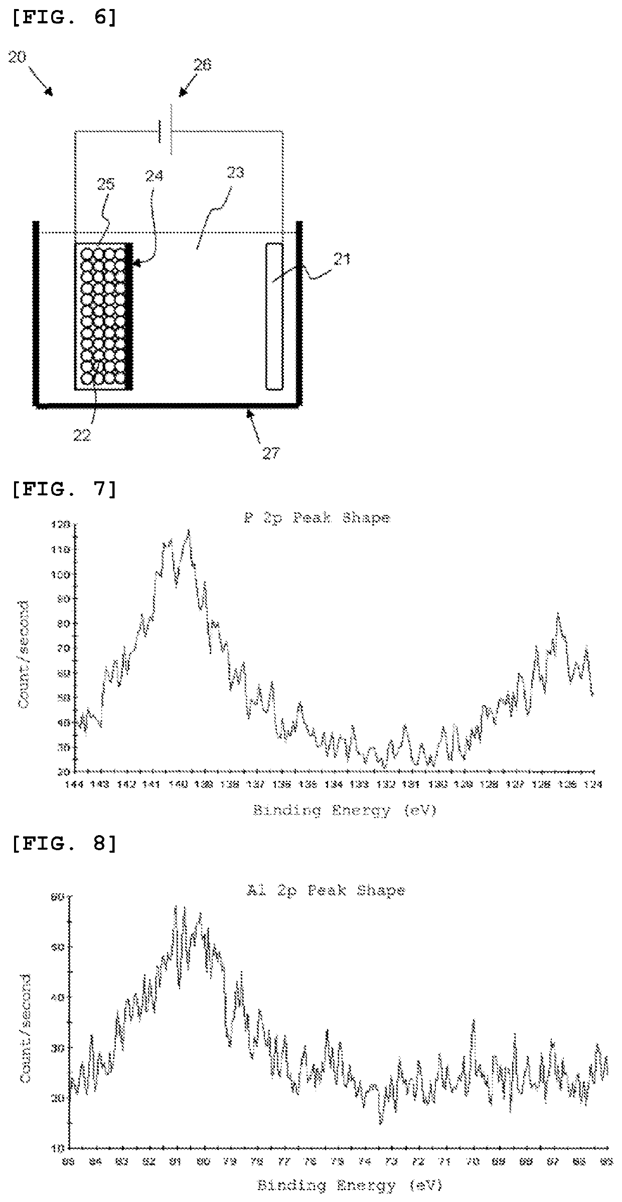
A negative electrode active material particle including: a silicon compound particle containing a silicon compound that contains oxygen, wherein the silicon compound particle contains a Li compound; and the negative electrode active material particle including aluminum phosphorous composite oxide attached to at least part of the surface, wherein the aluminum phosphorous composite oxide is a composite of P2O5 and Al2O3, and the P2O5 and the Al2O3 are in a mass ratio in a range of 1.2<mass of the P2O5 / mass of the Al2O3<3.0, wherein the negative electrode active material particle including aluminum phosphorous composite oxide has at least one peak in a region of a binding energy of more than 135 eV and 144 eV or less in a P 2p peak shape given in an X-ray photoelectron spectroscopy.

Description

TECHNICAL FIELD[0001]The present invention relates to a negative electrode active material, a mixed negative electrode active material, and a method of producing a negative electrode active material.BACKGROUND ART[0002]In recent years, small electronic devices, represented by mobile terminals, have been widely used and urgently required to reduce the size and weight and to increase the life. Such requirement has advanced the development of particularly small, lightweight secondary batteries with higher energy density. These secondary batteries are considered to find application not only for small electronic devices but for large electronic devices such as, typically, automobiles as well as power storage systems such as, typically, houses.[0003]Among those, lithium-ion secondary batteries are easy to reduce the size and increase the capacity and have higher energy density than those of lead or nickel-cadmium batteries, receiving considerable attention.[0004]The lithium-ion secondary ...

Claims


Application Information

Patent Timeline
Patent Type & Authority Patents(United States)
IPC IPC(8): H01M4/36H01M4/131H01M4/485H01M10/0525H01M4/02H01M4/62
CPCH01M4/366H01M4/131H01M4/485H01M4/625H01M10/0525H01M2004/027Y02E60/10C01B25/36C01B33/32H01M4/364H01M4/483H01M4/587H01M4/62H01M10/052C01P2006/40C01P2004/80
Inventor HIROSE, TAKAKAZUMATSUNO, TAKUMISAKAI, REIKO
Owner SHIN ETSU CHEM IND CO LTD
Learn More