Exhaust gas purifying system and method

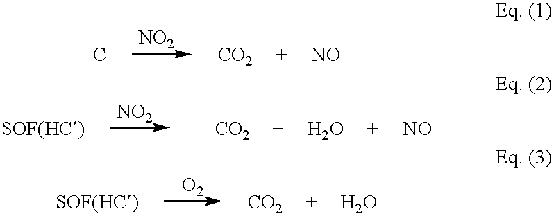
a technology of exhaust gas and purification system, which is applied in the direction of electrical control, physical/chemical process catalyst, separation process, etc., can solve the problems of difficult purification, insufficient purification of nitrogen oxides (nox), and inability to effectively achieve oxidation or removal of carbon particles (dry soot)

Inactive Publication Date: 2002-05-09
NISSAN MOTOR CO LTD
View PDF3 Cites 94 Cited by
  • Summary
  • Abstract
  • Description
  • Claims
  • Application Information

AI Technical Summary

Benefits of technology

[0014] Another object of the present invention is to provide an improved exhaust gas purifying system and method which can simultaneously remove five noxious components, NOx, HC, CO and PM (including SOF and soot) in exhaust gas, respectively at high efficiencies for a long time, under exhaust gas conditions in which low exhaust gas temperatures of not higher than 200.degree. C. frequently occur.
[0015] A further object of the present invention is to provide an improved exhaust gas purifying system and method by which NO.sub.2 existing in a limited amount in exhaust gas can be effectively used for combusting and removing dry soot upon separating SOF and dry soot in exhaust gas from each other and by treating separately SOF and dry soot.

Problems solved by technology

However, exhaust gas of the diesel engines (referred to as "diesel exhaust gas") is high in oxygen content as compared with conventional gasoline-fueled engines which are operated on air / fuel mixtures having air / fuel ratios around the stoichiometric value, so that purification of nitrogen oxides (NOx) becomes insufficient in case of using a conventional three-way catalyst.
In addition, exhaust gas of the diesel engines contains also particulate matter (PM), and therefore is difficult to be purified by using exhaust gas purifying catalysts of the conventional structures.
However, although the oxidizing catalysts mainly function to oxidize or remove carbon monoxide (CO) and hydrocarbons (HC) and may oxidize or remove soluble organic fraction (SOF) in the particulate matter to some extent, oxidation or removal of carbon particle (dry soot) as solid particle cannot be effectively accomplished.
Additionally, it has been pointed out that when the carried amount of platinum (Pt) serving as an active catalyst component in the exhaust gas purifying catalyst is increased in order to improve an oxidizing effect of the exhaust gas purifying catalyst particularly under low temperature conditions of not higher than 200.degree. C., a large amount of sulfate is produced upon an increase in exhaust gas temperature, which is disadvantageous.
However, in the conventional proposition, evaluation of the catalyst is carried out by using n-hexadecane as an imitation component for SOF, and therefore evaluation of the catalyst on actual gas containing high boiling point components having 20 or more in number of C is not accomplished while combustibility of dry soot (carbon) is not apparent.
Additionally, in the above Review, although the reducing (removing) efficiency to NOx is confirmed during a vehicle cruising mode, the confirmed reducing efficiency is not necessarily sufficient.
Thus, this proposition requires a complicated system and therefore is difficult to be applied to small-sized automotive vehicles.
However, in the present status, there exist limitations for applying the above method, so that a range within the limitations is relatively narrow.
For example, a temperature range in which conversion of NO into NO.sub.2 can be made is so limited as to be difficult to occur in a temperature condition of not higher than 200.degree. C.
Additionally, it is difficult to obtain a necessary amount of NO.sub.2 to be required for combustion of PM, while the problem of poisoning with S in exhaust gas may arise.
However, this method requires to changeover the flow direction of exhaust gas in accordance with operating conditions of an internal combustion engine, which is complicated.
In other words, the above method in Japanese Patent Provisional Publication No. 7-189656 uses an oxidizing catalyst similarly to conventional methods; however, the conventional methods are not provided with a measure for preferentially combusting SOF in an oxidizing catalyst, and additionally no consideration is taken on adhesion of soot so that it is not apparent as to whether the oxidizing catalyst is durable or not in a low exhaust gas temperature condition and in use for a long time.
Further, in case of using a complicated system for raising an exhaust gas temperature under controlling a throttle valve of an internal combustion engine, with the above method, the following problems will arise: First, it is unclear as to whether heat generation in the upstream trap having the function of an oxidizing catalyst can supply a sufficient quantity of heat to completely combust incombustible PM on the downstream trap.
Second, there are apprehensions of occurrence of a thermal deterioration of catalyst components, and of disadvantages due to control of the throttle valve.
Additionally, it is not apparent as to whether the traps is endurable or not to use for a long time.
Also in this case, there are apprehensions of thermal deterioration of catalyst components and fuel economy degradation due to supply of fuel.
However, no consideration is taken on removal of particle such as particulate matter discharged from an automotive vehicle engine and on a continuous regeneration of the filter.
Additionally, heat resistance, particulate trapping and combustion characteristics of the filter are unclear.
However, no consideration is taken on removable of particles and on a continuous regeneration of the filter.
Additionally, applicability of the filter to exhaust gas of an automotive vehicle engine is unclear.
As discussed above, removal of NOx is difficult in the conditions of diesel exhaust gas in which discharging exhaust gas at temperatures not higher than 200.degree. C. frequently occurs.
Additionally, oxidizing removal of HC and CO is insufficient in the above conventional oxidizing catalysts.
Furthermore, in case of using the filter or the filter in combination with the catalyst components, the complicated system including the device for accomplish the throttle valve control in the internal combustion engine or the heater is required.
Even in case of using the continuously regenerating trap in combination with the oxidizing catalyst, combustion reaction for PM is not possible over all vehicle cruising mode conditions.
Particularly in the low exhaust gas temperature condition of not higher than 200.degree. C., PM cannot be combusted so that the filter will be clogged with PM.
Moreover, a variety of techniques for removing each of NOx, HC, CO and PM (including SOF and soot) have been proposed; however, a so-called five-way exhaust gas purifying system for simultaneously removing the above five noxious components at high efficiencies has not yet been put into practical use.
(1) cannot be sufficiently made, and therefore C remains unburned thereby clogging the pores of a filter (section) of the filter catalyst.
More specifically, in such a low exhaust gas temperature condition, HC and CO are preferentially adsorbed on the catalyst over accomplishing reduction for adsorbed NOx, so that a sufficient NOx reduction rate may not be obtained.
If the rate of hydrogen relative to all reducing components is smaller than 0.5, adsorption of HC and CO) becomes predominant, and therefore a sufficient NOx reducing rate cannot be obtained.
If the ratio is smaller than 0.7, the effect for releasing sulfur is insufficient.

Method used


Image

  • Exhaust gas purifying system and method
  • Exhaust gas purifying system and method
  • Exhaust gas purifying system and method

Examples


example 1

[0060] (1) Production of Flow-through monolithic carrier for combustion of SOF

[0061] Porous silica having a specific surface area of about 830 m.sup.2 / g and an average pore size of about 3.2 nm was impregnated with an aqueous solution of lanthanum nitrate and an aqueous solution of dinitrodiammine platinum (Pt) having a Pt concentration of about 4% by weight thereby obtaining powdered impregnated porous silica which carried 4.0% by weight of Pt and 1.0% by weight of La. The powdered impregnated silica was mixed with boehmite powder in a weight ratio of 3 (silica):1 (boehmite powder), followed by adding 1% by weight of nitric acid-acidic alumina sol, thereby forming a mixture. The mixture was mixed with water and then pulverized for 60 minutes in a porcelain ball mill pot provided with alumina balls each having a diameter of 7 mm, thus obtaining a slurry.

[0062] This slurry was coated on a cordierite ceramic honeycomb monolithic substrate (having the trade name of HONEYCERAM(R), produ...

examples 2 to 5

[0068] Flow-through monolithic catalysts for combustion of SOF, of Examples 2 to 5 were produced by repeating the procedure (1) in Example 1 with the exception that aqueous solutions of cerium nitrate, iron nitrate, magnesium nitrate and zirconyl nitrate are respectively used in Examples 2, 3, 4 and 5, in place of the aqueous solution of lanthanum nitrate.

[0069] Filter catalysts formed of fiber, of Examples 2 to 5 were produced by repeating the procedure (2) in Example 1.

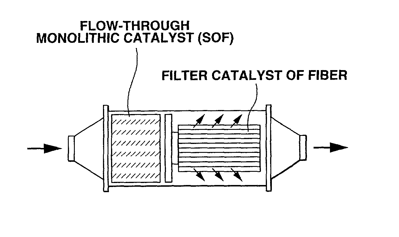
[0070] Each of the thus produced flow-through monolithic catalyst (for combustion of SOF) and each of the thus produced cylindrical filter catalyst were arranged in series and set in a casing as shown in FIG. 1 in which the monolithic catalyst and the filter catalyst were located respectively on upstream and downstream sides relative to flow of exhaust gas, thereby preparing respectively an exhaust gas purifying systems 2, 3, 4 and 5 of Examples 2, 3, 4 and 5.

examples 6 to 9

[0071] Flow-through monolithic catalysts for combustion of SOF, of Examples 6 to 9 were produced by repeating the procedure (1) in Example 1.

[0072] Filter catalysts formed of fiber, of Examples 6 to 9 were produced by repeating the procedure (2) in Example 1 with the exception that aqueous solutions of lanthanum nitrate, iron nitrate, magnesium nitrate and potassium nitrate were respectively used in Examples 6, 7, 8 and 9, in place of the aqueous solution of cerium nitrate.

[0073] Each of the thus produced flow-through monolithic catalyst (for combustion of SOF) and each of the thus produced cylindrical filter catalyst were arranged in series and set in a casing as shown in FIG. 1 in which the monolithic catalyst and the filter catalyst were located respectively on upstream and downstream sides relative to flow of exhaust gas, thereby preparing respective exhaust gas purifying systems 6, 7, 8 and 9 of Examples 6, 7, 8 and 9.


PUM

PropertyMeasurementUnit
temperatureaaaaaaaaaa
pore sizeaaaaaaaaaa
specific surface areaaaaaaaaaaa

Abstract

An exhaust gas purifying system for an automotive internal combustion engine. The exhaust gas purifying system comprises a flow-through monolithic catalyst disposed in an exhaust gas passageway through which exhaust gas flows. The monolithic catalyst functions to adsorb and oxidize a soluble organic fraction in exhaust gas, to adsorb nitrogen oxides in exhaust gas in a condition in which a temperature of exhaust gas is not higher than 200° C. and to allow carbon particle in exhaust gas to pass through the monolithic catalyst. Additionally, a filter catalyst is disposed in the exhaust gas passageway downstream of the flow-through monolithic catalyst. The filter catalyst functions to trap the carbon particle and to oxidize hydrocarbons, carbon monoxide and nitrogen monoxide in exhaust gas.

Description

BACKGROUND OF INVENTION[0001] This invention relates to improvements in exhaust gas purifying system and method, and more particularly to the exhaust gas purifying system and method for removing five noxious components, NOx, HC, CO and PM (including SOF and soot) in exhaust gas such as one discharged from a diesel engine, at high efficiencies.[0002] In recent years, lean-burn engines which are mainly operated on air-fuel mixture having air-fuel ratios richer than a stoichiometric value have been spread from the view points of improving fuel economy and reducing an amount of emission of carbon dioxide. Attention on the lean-burn engines have been paid particularly for diesel engines because of a high fuel economy characteristics in the lean-burn engines. However, exhaust gas of the diesel engines (referred to as "diesel exhaust gas") is high in oxygen content as compared with conventional gasoline-fueled engines which are operated on air / fuel mixtures having air / fuel ratios around th...

Claims


Application Information

Patent Timeline
Patent Type & Authority Applications(United States)
IPC IPC(8): F01N3/02B01D39/14B01D53/94B01J23/42B01J23/58B01J23/63B01J23/89B01J29/74B01J29/76B01J35/02B01J35/04B01J35/10B82Y30/00F01N3/022F01N3/023F01N3/035F01N3/08F01N3/22F01N3/24F01N3/28F01N13/02F02D41/04F02D41/14
CPCF01N3/0226F01N3/0231F01N3/035F01N13/0097F01N3/0821F01N3/0835F01N3/0842F01N3/0814
Inventor AKAMA, HIROSHIKANEKO, HIROAKIITOU, JUNJIKAMIJO, MOTOHISA
Owner NISSAN MOTOR CO LTD
Why Eureka
Try Eureka