
Rubber-reinforcing fiber, process for producing the same, and rubber product and pneumatic tire each made with the same

a technology of reinforcing fiber and rubber, which is applied in the direction of tyre parts, physical treatment, textiles and paper, etc., can solve the problems of low and insufficient adhesion of twisted cords (multifilament cords) to rubber, inability to meet geometric fiber structures suitable for achieving sufficient adhesive strength, and inability to achieve sufficient fatigue resistance. , to achieve the effect of improving the fatigue resistan

Inactive Publication Date: 2003-01-02
BRIDGESTONE CORP
View PDF4 Cites 43 Cited by
  • Summary
  • Abstract
  • Description
  • Claims
  • Application Information

AI Technical Summary

Benefits of technology

[0079] The polyester component may be added with a known additive such as a softening agent and a stabilizer in an amount not adversely affecting the effect of the invention, for example, 10% by weight or less.

Problems solved by technology

The prior art, however, fails to address the geometric fiber structure suitable for achieving a sufficient adhesive strength.
As a result, it has been found that the dry-plated cord is improved in handling workability, but the cord-to-rubber adhesion is still low and insufficient.
For this reason, the twisted cord (multifilament cord) is difficult to adhere to rubber by merely using the dry-plating.
Japanese Patent No. 2512913, however, reports that the results of the peeling test on the metal fiber materials made of steel cord or amorphous steel cord are 100% rubber failure.
As a result of the study made by the inventors, however, it has been found that a twisted cord made of an organic fiber material is poor in its adhesion to rubber as shown in the examples of the present invention.
As a result thereof, the adhesive failure occurs at filaments having a thin coating located inside of the bundle of filaments, thereby decreasing the adhesive strength.
As mentioned above, however, because of the insufficient fatigue resistance of the monofilament cord against the external force as compared with the twisted cord, a tire reinforced with the monofilament cord is low in its endurance and may cause problems during the practical use.
In driving endurance test, particularly, a cord break is sometimes caused on a tire having a carcass reinforced with a monofilament cord by a driving compression stress applied to a turn-up portion of the carcass around a bead portion because of the insufficient fatigue resistance of the monofilament cord.
However, the application of the monofilament cord treated by the steam heating to tires has not yet been put into practice.
The proposed monofilament cord is, however, still insufficient in the fatigue resistance against the physical fatigue during its use in tires, and there is a fear of cord failure during tire operation to cause practical problems.
When a known adhesive composition is used, however, the adhesion of a monofilament cord to rubber is inferior to that of a twisted cord to rubber.
This is because that, when immersed in a rubber-fiber adhesive composition such as RFL solution, the penetration of an adhesive composition into the space between filaments does not occur in the monofilament cord as in the case of a twisted cord, thereby failing to obtain a mechanical anchoring effect.
Additional problem of the monofilament cord in the adhesion properties is that the adhesive coating on the monofilament cord is thinner than that on a twisted cord because of a smaller surface roughness of the monofilament cord.
Therefore, the known dipping method in the adhesive composition is not suitable for the monofilament cord in view of its geometric structure, and the above problems should be solved to attain a stable adhesion properties of the monofilament.
In addition, with the recent increasing improvement in tire performance, the strain applied to a tire cord during tire operation becomes severe and more severer.
Under such a severe condition, the polyester monofilament treated with RFL proposed in Japanese Patent Application Laid-Open No. 9-67732 referred to above is likely to become insufficient in the durability of the interfacial adhesion between fiber and rubber, because such a monofilament shows a relatively low adhesive property when deficient in mechanical anchor.
Heat-fusible resins, however, are limited to thermoplastic resins which are softened at relatively low temperatures.
Thus, a thermoplastic resin is not necessarily suitable for reinforcing a rubber efficiently.
If short fibers are made of a material having a high melting point, particularly, having a melting point higher than the highest process temperature, such as the vulcanization temperature, in the manufacture of rubber articles, the resin is not softened and the heat fusion of the short fibers becomes difficult.
In such a method, however, the adhesive composition causes the short fibers to come together, resulting in a practical problem of sticking between the short fibers before dispersing the short fibers throughout a rubber.
As mentioned above, a hard-to-adhere fiber having a dense molecular structure and a small number of functional groups is difficult to bond to rubber by a known adhesive composition and shows a low fatigue resistance.
Therefore, there has been a demand for a rubber reinforcing short fiber capable of forming a firm adhesion to rubber and free from a reduction of workability by sticking due to an adhesive composition, even when the short fiber is difficult to adhere because of its high elastic modulus and high melting point, or the short fiber is low-melting but difficult to be heat-fused because of its poor compatibility with a rubber.

Method used

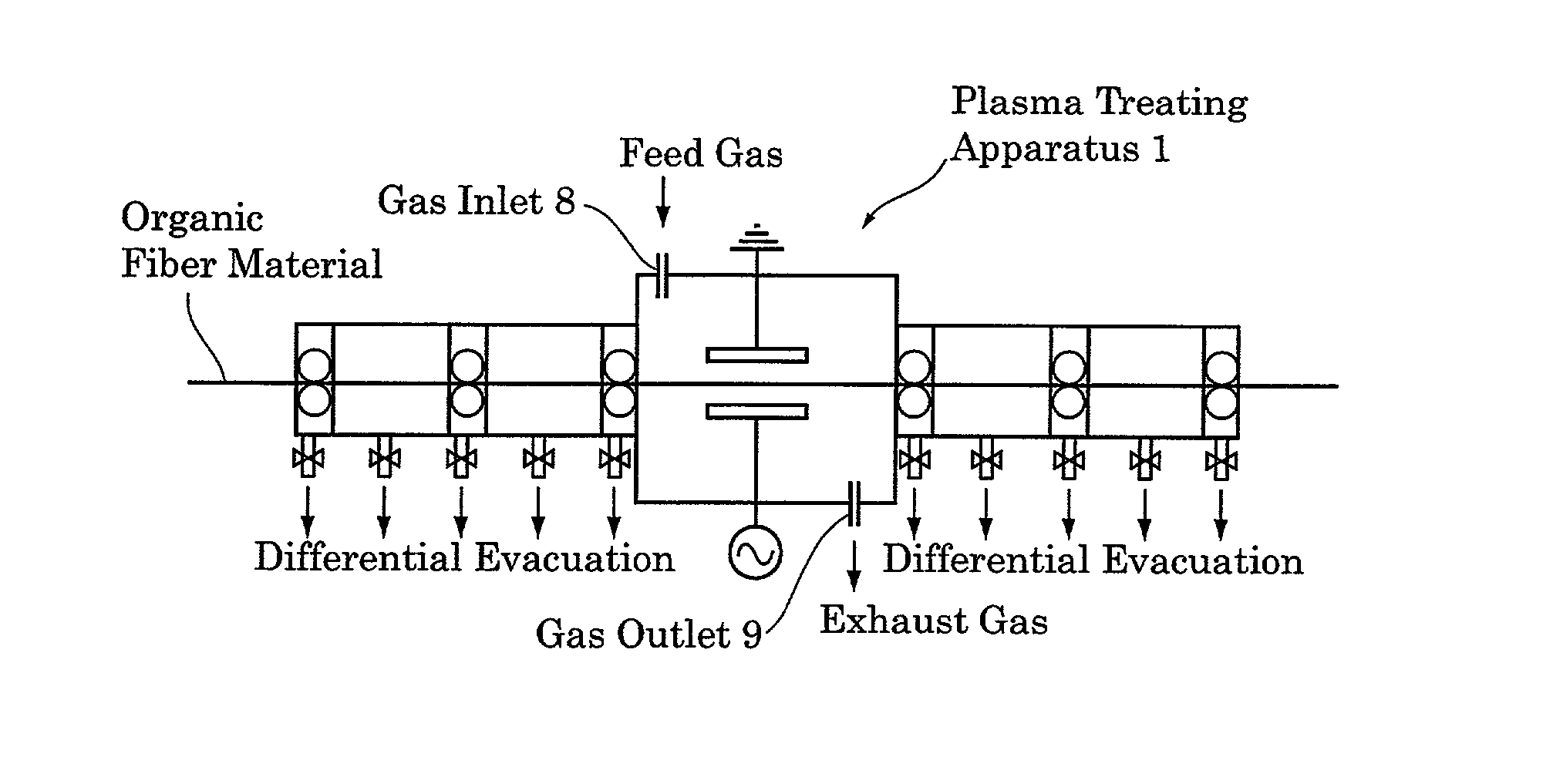
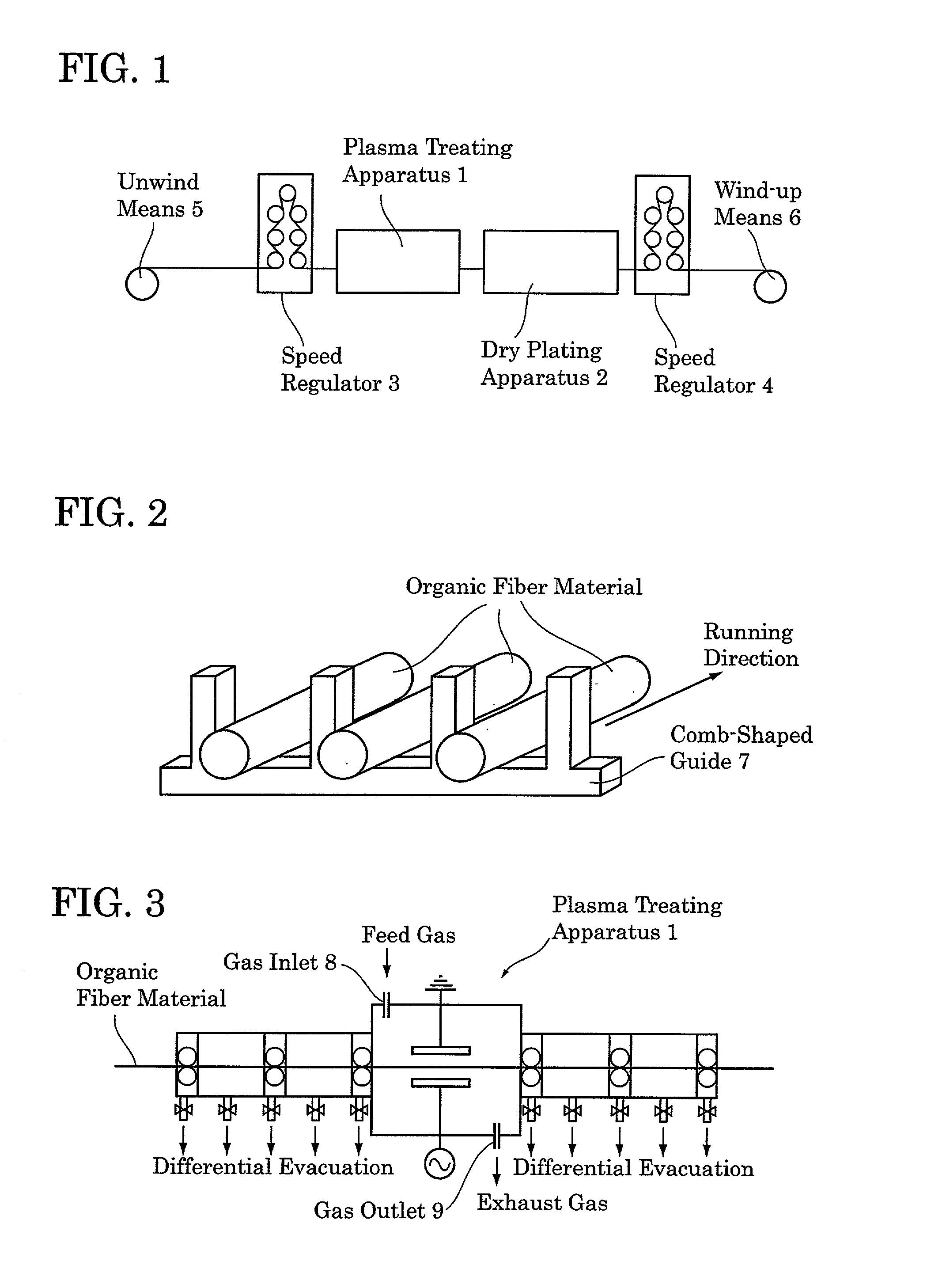
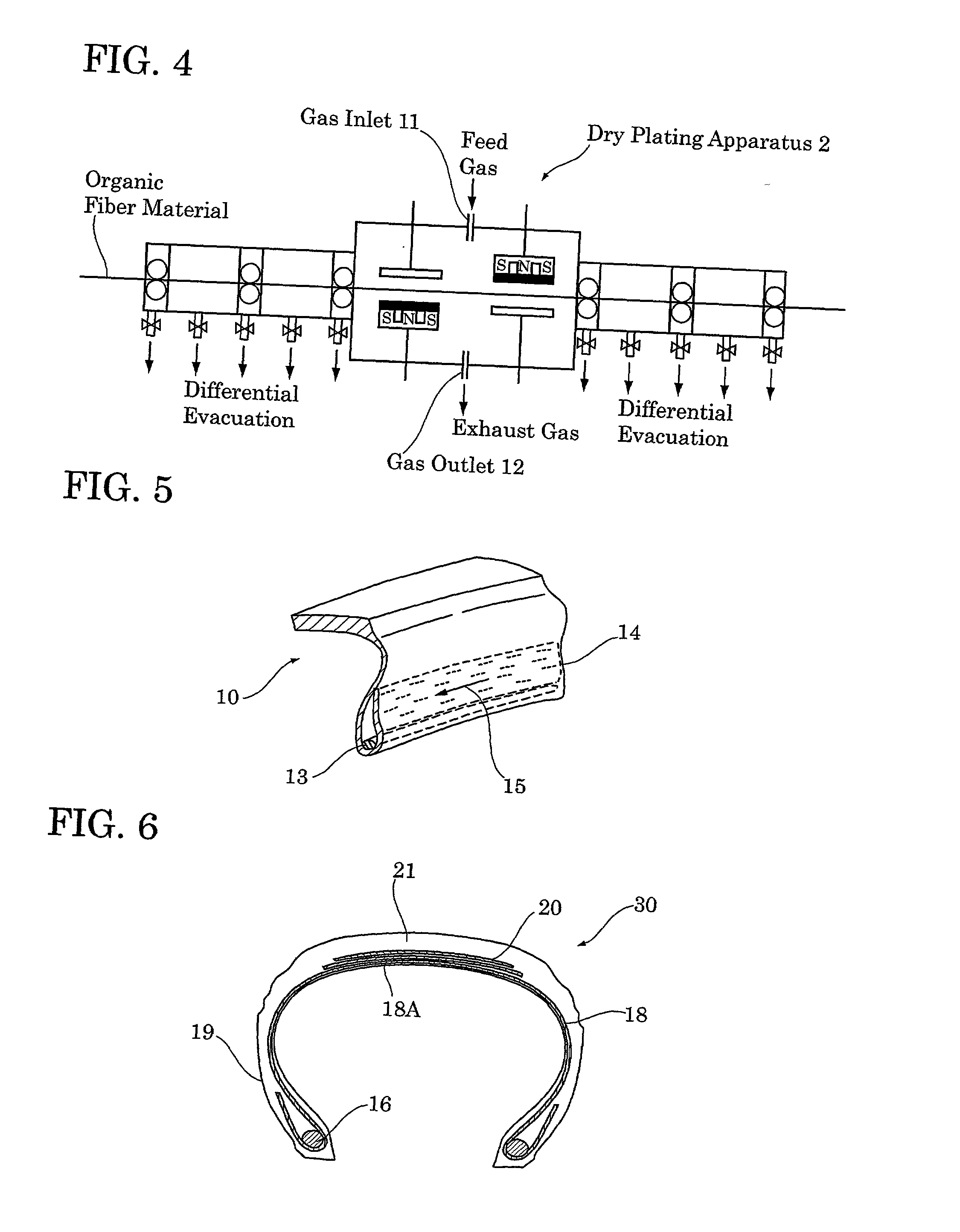

Image

  • Rubber-reinforcing fiber, process for producing the same, and rubber product and pneumatic tire each made with the same
  • Rubber-reinforcing fiber, process for producing the same, and rubber product and pneumatic tire each made with the same
  • Rubber-reinforcing fiber, process for producing the same, and rubber product and pneumatic tire each made with the same

Examples


preparation example 2

[0236] Poly(Ethylene Terephthalate) Multifilament F-2

[0237] A poly(ethylene terephthalate) multimonofilament was prepared by twisting the poly(ethylene terephthalate) monofilaments of Preparation Example 1 at 25 turns / 10 cm by a twisting machine.

preparation example 3

[0238] Poly(Vinyl Alcohol) Monofilament F-8

[0239] A 40% poly(vinyl alcohol) (PVA) solution in dimethyl sulfoxide (DMSO) was prepared by dissolving PVA (vinyl alcohol unit: 81 mol %, vinyl acetate unit: 19 mol %, polymerization degree: 600, saponification degree: 80 mol %) in DMSO under stirring at 90.degree. C. for 12 hours in a reduced nitrogen atmosphere of 100 Torr or lower. The solution was extruded from an extruder kept at 90.degree. C. through a nozzle of 0.55 mm diameter and drawn in an acetone / DMSO mixture (95 / 5 by weight) kept at 2.degree. C. By removing the remaining DMSO by extraction into hot acetone and drying at 80.degree. C. by a hot-air drier, a PVA monofilament having a single fiber diameter of 120 .mu.m and the melting point of 191.degree. C. was obtained.

preparation example 4

[0240] Acrylic Monofilament F-9

[0241] A 9 wt % polymer solution was prepared by dissolving a polymer consisting of 95 mol % acrylonitrile unit and 5 mol % methyl acrylate unit into a 60 wt % dense aqueous solution of zinc chloride. The solution was pressed into a 25 wt % aqueous solution of zinc chloride through a nozzle having 12,000 holes of 0.06 mm diameter. The strands were drawn 2.5 times during the washing with water for removing the solvent, dried, and re-drawn 5 times in a saturated steam at 105.degree. C., thereby obtaining acrylic multifilament having a single fiber diameter of 10 .mu.m. The acrylic monofilament was obtained by drawing a desired amount from the multifilament.


PUM

PropertyMeasurementUnit
Lengthaaaaaaaaaa
Lengthaaaaaaaaaa
Lengthaaaaaaaaaa

Abstract

The rubber-reinforcing fiber of the present invention is provided with a coating layer of a thickness of 10 Å to 40 mum. The coating layer is formed by dry plating and contains at least one metal and / or metal compound selected from the group consisting of cobalt, zinc, copper, titanium, silver, nickel and compounds of the aforesaid metals. With such a coating layer, the rubber-reinforcing fiber of the present invention forms a firm adhesion to a rubber component and drastically improves the fatigue resistance and durability of a rubber article, particularly, a pneumatic tire.

Description

[0001] The present invention relates to a rubber-reinforcing fiber which is coated with a layer containing a metal or a metal compound so as to show an excellent fatigue resistance during its use in rubber, a method for producing the rubber-reinforcing fiber, and a rubber article and a pneumatic tire reinforced with the rubber-reinforcing fiber.[0002] Various composite materials comprising a reinforcing material and a rubber have been used in the production of a pneumatic tire, a belt conveyer, etc. An indispensable requirement for such composite materials is a firm adhesion between the reinforcing material and the rubber.[0003] To meet the requirement, Japanese Patent Application Laid-Open No. 62-87310 assigned to the same assignee as that of this application proposes a method for producing a substrate-rubber composite, in which a firm substrate-to-rubber bonding upon vulcanization is achieved by depositing a thin metal film mainly comprising zinc and copper on the substrate by dry...

Claims


Application Information

Patent Timeline
IPC IPC(8): B29B15/14B60C1/00B60C9/00B60C9/08B60C15/06C03C25/10C03C25/27C03C25/46C08J5/06D06M10/02D06M11/83D06M15/693
CPCB29D2030/481Y10T152/1081B60C1/00B60C9/0042B60C9/08B60C15/06C03C25/1015C03C25/46C08J5/06C08J2321/00D06M10/025D06M11/83D06M15/693D06M2200/50B29B15/14B29B15/08B29B15/12B60C9/0064B29L2030/003C03C25/27
Inventor NAKAMURA, MASAAKIYOSHIKAWA, MASATO
Owner BRIDGESTONE CORP
Learn More