
Synthesis of YBa2Cu3O7 using sub-atmospheric processing

a sub-atmospheric processing and synthesis technology, applied in the direction of superconductor devices, superconductor devices, vacuum evaporation coating, etc., can solve the problems of high equipment requirements, high cost, and low growth rate of ybco film synthesis techniques

Inactive Publication Date: 2003-03-13
BROOKHAVEN SCI ASSOCS
View PDF8 Cites 31 Cited by
  • Summary
  • Abstract
  • Description
  • Claims
  • Application Information

AI Technical Summary

Problems solved by technology

Unfortunately both of these techniques for making crystalline YBCO films have drawbacks.
One drawback is that the YBCO film growth rate is low.
In addition the equipment required for delivering the humidified gas to the heat-treating furnace becomes more complex and costly.
Finally, it is difficult to grow large area films with uniform properties using atmospheric pressure heat-treating.
However, Horwitz et al. only disclose manganite film structures.
However, it was found that films made by coevaporation using a Ba metal source quickly degraded in the presence of moisture.
This greatly complicates the operation and maintenance of a vacuum deposition system.
Therefore, these processes required extreme care and the resulting films were difficult to reproduce on a routine basis.
In addition, the bulk material was found to be sensitive to environmental conditions, especially water, indicating that the films required special handling to ensure stability.
The use of one atmosphere of pressure in a BaF.sub.2 post annealing process presents a number of problems, both real and potential.
These films were grown at rates of up to 2.5 Angstroms per second but unfortunately required extremely high water vapor partial pressures, on the order of 150 Torr.
Such high water vapor pressures can have a deleterious effect on a metallic substrate, a buffer layer and a YBCO film especially at a typical heat-treating temperature of 735.degree. C.
For example metallic substrates become more susceptible to oxidation as the water vapor pressure is increased.

Method used


Image

  • Synthesis of YBa2Cu3O7 using sub-atmospheric processing
  • Synthesis of YBa2Cu3O7 using sub-atmospheric processing
  • Synthesis of YBa2Cu3O7 using sub-atmospheric processing

Examples


example 2

[0058] Example 2 demonstrates the processing conditions used to grow an YBCO film at a rate in excess of 15 .ANG. / sec.

[0059] A precursor film comprising Ba, Y, Cu and F was formed in a vacuum deposition chamber in a vacuum of about 10.sup.-6 Torr. The BaF.sub.2 was evaporated using a thermal source at a deposition rate of 50 .ANG. / sec. The Y and Cu metals were evaporated using electron beam guns at deposition rates of 20 and 32 .ANG. / sec respectively. The precursor film was deposited onto a SrTiO.sub.3 single crystal substrate with a 001 face cut at a rate of 100 .ANG. / sec. The substrate was 3.times.10.times.1 millimeters in size and was not intentionally heated during the deposition. The resulting film was comprised of microcrystalline BaF.sub.2, Y and Cu, or possibly oxides of Y and Cu, as revealed by Transmission Electron Microscopy.

[0060] After the deposition was completed the precursor film was removed from the vacuum deposition chamber. Silver contacts were attached to the fil...

example 3

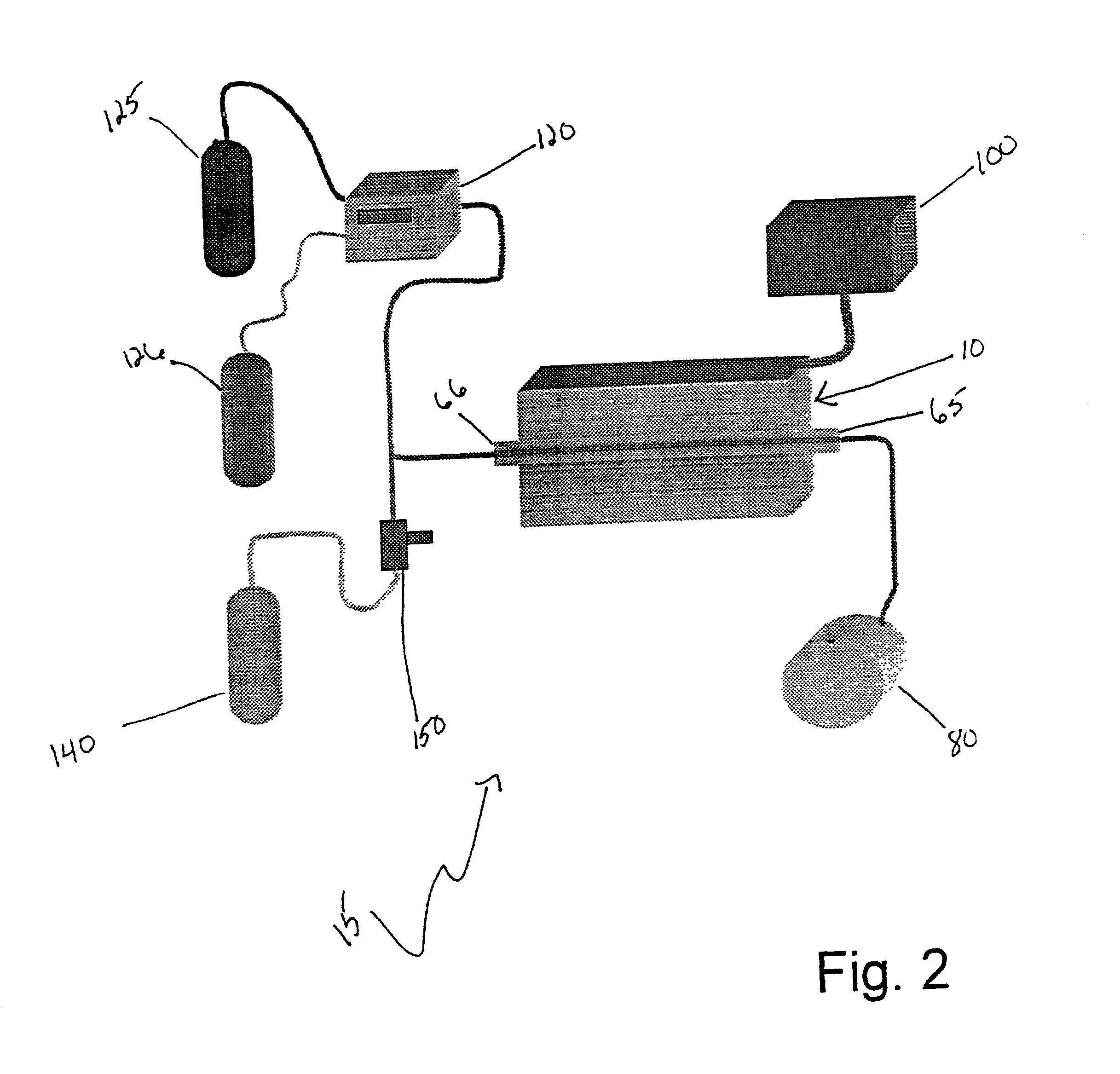
[0064] In Example 1 and Example 2 the precursor film 85 was heat-treated in a quartz tube 50 centimeters in diameter and 150 centimeters long as shown schematically in FIG. 3. In order to demonstrate the utility of the present invention Example 3 describes the growth of an YBCO film 85 wherein the vacuum-processing apparatus 15 was modified. It was desired to heat-treat a precursor film 85 at a water vapor pressure of 5 Torr and a total pressure of 21 Torr. Normally the YBCO growth rate in our vacuum-processing apparatus 15 for these sub-atmospheric pressure conditions would be in excess 10 .ANG. / sec as indicated in FIG. 4. It was desired to lower the YBCO growth rate without appreciably altering the water vapor pressure of 5 Torr and the total pressure of 21 Torr. The vacuum-processing apparatus 15 was modified as follows; a container 70 was constructed and placed in the quartz tube 60 of the vacuum-processing apparatus 15. The container 70 is shown schematically in FIG. 7. The fun...

example 4

[0074] Example 2 demonstrates the processing conditions used to grow an YBCO film on a flexible substrate.

[0075] A precursor film comprising Ba, Y, Cu and F was formed in a vacuum deposition chamber in a vacuum of about 10.sup.-6 Torr in the same manner as described in Example 1. The precursor film was deposited onto a flexible substrate. The flexible substrate was a composite structure consisting of, first a textured nickel base, which had deposited on the nickel base a first heteroepitaxial layer of cerium oxide (CeO.sub.2), which had deposited on the CeO.sub.2 a second heteroepitaxial layer of yttrium stabilized zirconia (YSZ), which had deposited on the YSZ a third heteroepitaxial layer of CeO.sub.2.

[0076] After the deposition was completed the precursor film was removed from the vacuum deposition chamber. The precursor film was mounted in a container 70 similar to the container 70 shown in FIG. 7 and the precursor film-container 70 combination was inserted into the quartz tube ...


PUM

PropertyMeasurementUnit
temperatureaaaaaaaaaa
thicknessaaaaaaaaaa

Abstract

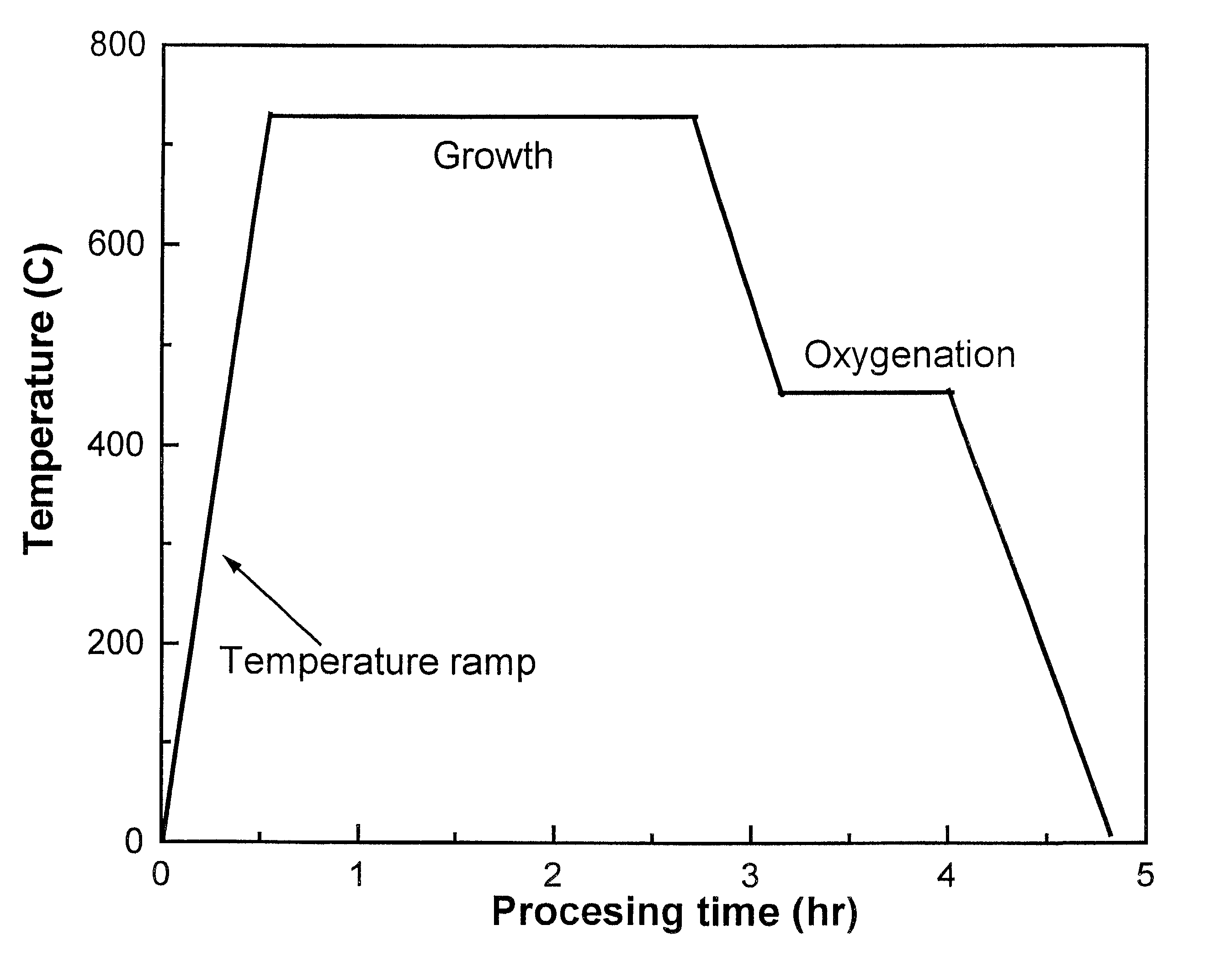
The present invention is a method of forming thick films of crystalline YBa2Cu3O7 that includes forming a precursor film comprising barium fluoride (BaF2), yttrium (Y) and copper (Cu). The precursor film is heat-treated at a temperature above 500° C. in the presence of oxygen, nitrogen and water vapor at sub-atmospheric pressure to form a crystalline structure. The crystalline structure is then annealed at about 500° C. in the presence of oxygen to form the crystalline YBa2Cu3O7 film. The YBa2Cu3O7 film formed by this method has a resistivity of from about 100 to about 600 muOhm-cm at room temperature and a critical current density measured at 77 K in a magnetic field of 1 Tesla of about 1.0x10⁵ Ampere per square centimeter (0.1 MA / cm2) or greater.

Description

BACKGROUND OF INVENTION[0002] The present invention relates to methods for making high-performance superconducting materials. In particular, the present invention relates to a method for making films of biaxially textured YBa.sub.2Cu.sub.3O.sub.7 ("YBCO") on flexible substrates.[0003] The recent discovery of a broad class of materials such as YBCO with superconducting transition temperatures exceeding the boiling point of liquid nitrogen (77 K) has resulted in widespread interest in developing methods for making these materials and finding new applications for them. YBCO is useful for the fabrication of high frequency filters, SQUIDS and other electronic devices. In addition it has promise as a conductor for use in electric motors, electrical cable, transformers, fault current limiters and various electrical utility devices. One of the most promising applications of high critical temperature superconductors is for use in the fabrication of high field magnets. The fabrication of magn...

Claims


Application Information

Patent Timeline
Patent Type & Authority Applications(United States)
IPC IPC(8): C04B35/45C23C14/06C23C14/58H10N60/01
CPCC04B35/4508C04B35/64C04B2235/3213C04B2235/3225C04B2235/3281C04B2235/445C04B2235/6581C04B2235/663C04B2235/96C23C14/0694C23C14/5853H01L39/2451H10N60/0548
Inventor WIESMANN, HAROLDSOLOVYOV, VYACHESLAV
Owner BROOKHAVEN SCI ASSOCS
Learn More