[0017] The present invention is directed to a thermally-conductive interface, and a material therefor, for a thermal management
assembly involving, for example, a heat source such as an
electronic chip or other heat-generating component and a
thermal dissipation member such as a
heat sink or spreader disposable in thermal adjacency with the
electronic component for the conduction of heat therebetween. Particularly, the invention is directed to a material in the form of a thermally-conductive compound which may be provided as a sheet or pad, and / or which may be dispensable, such under an applied pressure as issued as a bead or
mass from a
nozzle or other orifice, for forming an interlayer which is compliant or otherwise conformable between the
interfacing surfaces of the electronic component and the
heat sink or spreader to provide a low thermal impedance across the
assembly, and which affords lower thermal impedance for improved heat transfer performance.
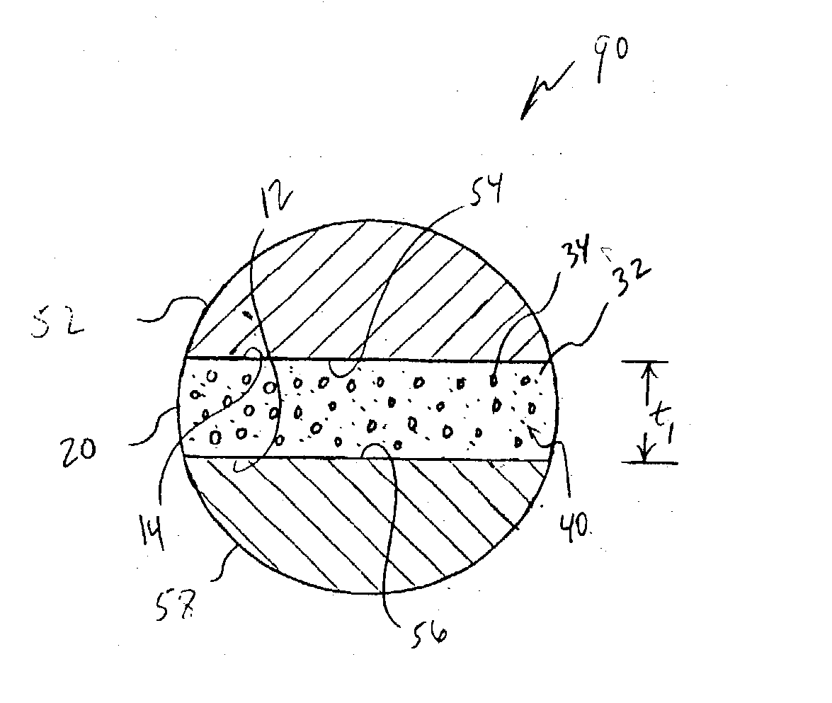
[0047] Following the heating of the layer 20 to a temperature which is above the
phase transition temperature of the fusible
metal or
alloy, the domains 34 may form an
emulsion with the matrix phase 32. Advantageously, however, by virtue of the
thermal grease matrix, the
viscosity (absolute or intrinsic) of the emulsified compound may be maintained to be, for example, between about 10,000-300,000 cp (10-300 Pa-s) within the
operating temperature range of the electronic component involved, or otherwise between about 40-80.degree. C., such that the
emulsion is sufficiently viscous to remain in the bondline. Moreover, it has been observed that the addition of
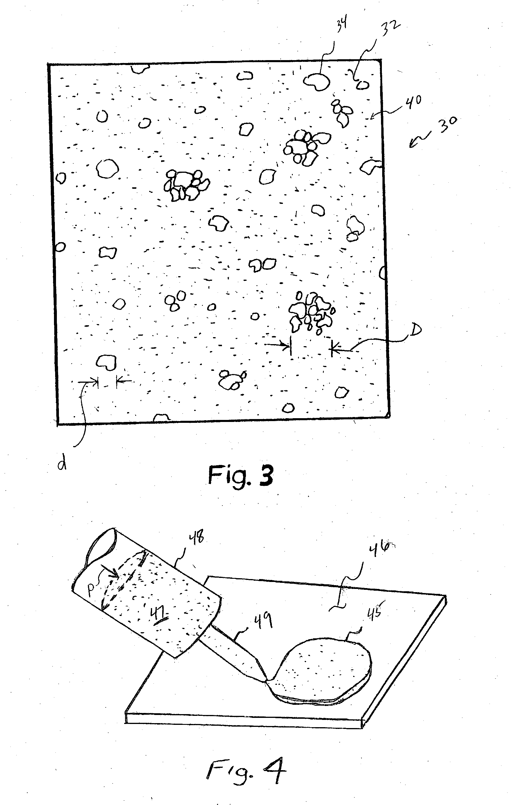
alumina,
boron nitride, or other thermally-conductive filler particles to the formulation, although not necessarily required, provides optimal thermal performance in that the filler particles 40 may function as a
thermal bridge between the domains 34 of the dispersed phase component giving the apparent effect of domain to domain contact along a thermal path or network. Such filler particles also can be used to modify the
viscosity, and hence to control the flow, of the compound.
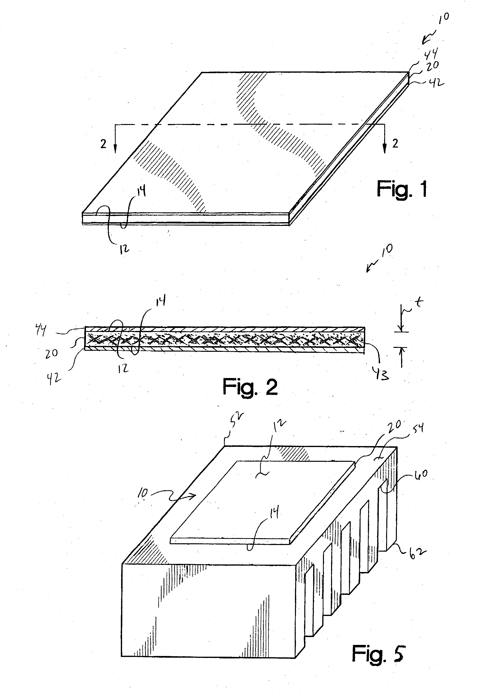
[0050] Although not required, a carrier or reinforcement member, referenced at 43 in FIG. 2, optionally may be incorporated within layer 20 as an interlayer therewithin, as shown, or alternatively on one or both of the surfaces 12 and 14 to provide increased
tear resistance. In either arrangement, the member 43 may be formed as having interstices or holes within which the thermally-conductive compound may be impregnated otherwise carried. Particularly, such member 43 may be provided as a film formed of a
thermoplastic material such as a
polyimide or polyetheretherketone (PEEK), a layer of a woven or non-woven, e.g., needled, fiberglass fabric, cloth, web, or mat, or an aluminum or other
metal foil, screen, or expanded mesh. In addition to functioning as a carrier for the compound, the reinforcement also may be used to improve the
physical strength of the layer 20 and pad 10 to better facilitate handling at higher ambient temperatures and
die cutting into a variety of geometries. The reinforcement member typically will have a thickness of between about 0.5-5 mil (12.5-125 82 m), with a thickness of about 1-2 mils (25-50 .mu.m) being preferred for metal foils.
[0062] With reference next to the depiction at 90' shown in FIG. 7B, upon heating and the
resultant phase change of the dispersed domains 34 into their conformable second phases, which phases may form an
emulsion with the
thermal grease component of the matrix phase 32, an even thinner MBLT, now referenced at t.sub.2, between the surfaces 54 and 56 may be achieved. The thickness t.sub.2 may be reduced, such as under the continuing application of the given applied
external pressure which may be developed from a spring clip or the like, by about 20-50% or more as compared to the thickness t.sub.1, with a corresponding increase in the surface area of pad 10 which thereby may flow to substantially fill the margins of the bondline gap between the surfaces 54 and 56, and a correspondingly decreased thermal impedance.

