Fabrication method of carbon nanotubes

Inactive Publication Date: 2004-02-26
TOHOKU TECHNO ARCH CO LTD
View PDF6 Cites 30 Cited by
  • Summary
  • Abstract
  • Description
  • Claims
  • Application Information

AI Technical Summary

Benefits of technology

0009] With this procedure, an individual carbon nanotube can b

Problems solved by technology

This technique has problems that it requires a grea

Method used


Image

  • Fabrication method of carbon nanotubes
  • Fabrication method of carbon nanotubes
  • Fabrication method of carbon nanotubes

Examples


examples

[0033]

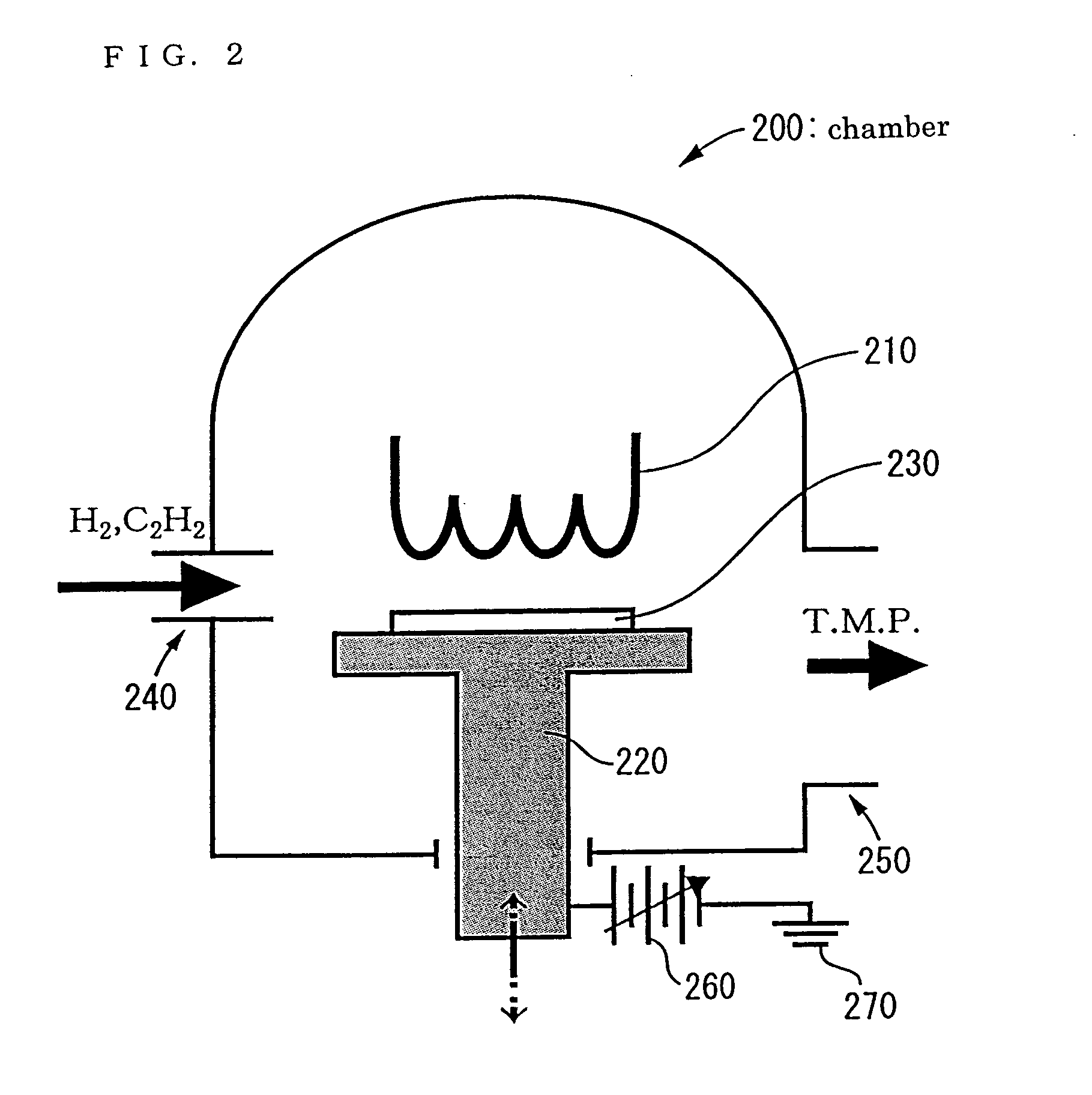
[0034] In following example for fabricating a probe tip, if there is no description, the HF-GVD was performed by following condition. Acetylene (C.sub.2H.sub.2) gas diluted by hydrogen (H.sub.2) was employed as a source gas. The partial pressure of acetylene and hydrogen are 3, 27 Pa, respectively. Tungsten wire with a diameter of 0.6 mm was used as the hot-filament.

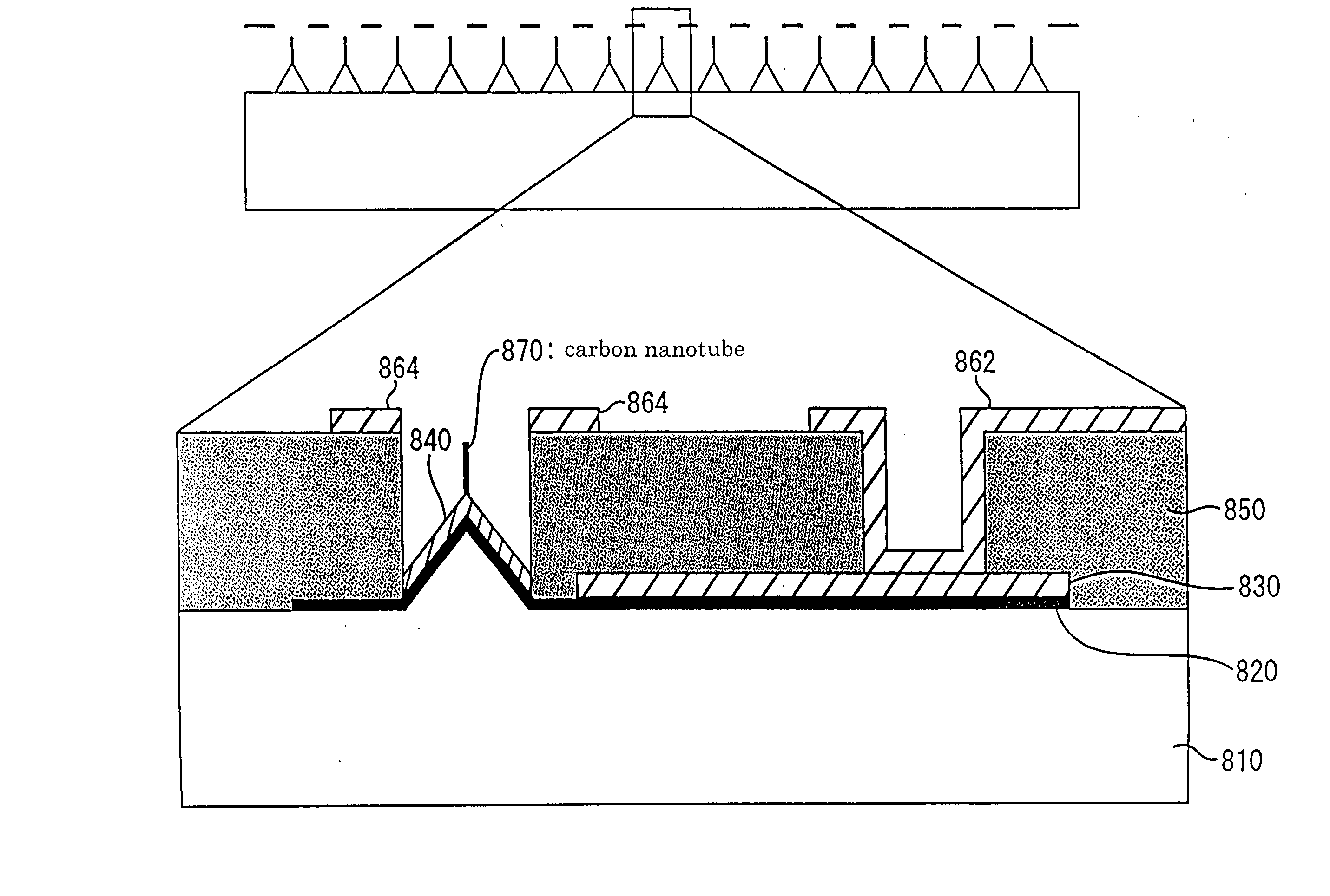
[0035] During the growth, the tungsten filament 210 was heated at 1900.degree. C. by flowing a current and the temperature was measured by a pyrometer from the outside of the chamber 200. The distance between the filament 210 and the substrate 230 was adjusted to be about 5 mm with a Z-linear motion mechanism. As a sample specimen, a commercial SPM probe made of silicon was used. Prior to the CVD growth, several-nm thick nickel was deposited entirely on the sample. The CVD process was done for 15 min.

[0036] FIG. 3 shows the process flow of an individual carbon nanotube using the commercial probe (FIG. 3(a)). A 5-n...


PUM


Abstract

In this invention, protrusions are formed on a substrate such as silicon and quartz glass, and catalytic metal of transition element, such as nickel, iron and cobalt are coated on the substrate, and carbon nanotubes are grown by hot-filament chemical vapor deposition or microwave-plasma enhanced chemical vapor deposition under an application of negative voltage to the substrate. Where the substrate is heated. In these methods, carbon nanotubes can be selectively grown from the apex of protrusions. As a substrate, silicon probe for scanning probe microscopy (SPM) can be used. The carbon nanotube probe can be applied to high resolution SPM probe for imaging a precise topographic image.

Description

[0001] This invention involves the fabrication and selective growth of carbon nanotubes (CNTs) for applications of scanning probe microscopy (SPM) probes, field emission display (FED) emitters.[0002] Carbon nanotubes (CNTs) are conductive nanostructures and easily emit electrons as a field emitter. Since the discovery of CNTs, many researches have been conducted and various unique properties originated in the inherent nanostructure have been found one after another. Especially the unique structures and the excellent mechanical properties have been attracted attention. The CNTs as can be seen from the name, have the structure as a graphene sheet with one or multi-layer rolls into a tubular. The structure shows high aspect ratio; the diameters are ranging from nm to several-tenth nm, and the length from micrometer to tenfold of micrometer. The high aspect ratio structure enable to concentrate a high electric filed at the end of CNTs, which is very advantageous for a field emitter as v...

Claims


Application Information

Patent Timeline
IPC IPC(8): B82B3/00C01B31/02C23C16/26C23C16/44G01Q60/38G01Q70/12G01Q70/16H01J1/30H01J1/304H01J9/02H01J9/04
CPCB82Y10/00B82Y15/00B82Y30/00H01J2329/00G01Q70/12H01J9/025H01J2201/30469B82Y35/00
Inventor ONO, TAKAHITOMASAYOSHI, ESASHI
Owner TOHOKU TECHNO ARCH CO LTD
Why Eureka
Try Eureka