Polymer electrolyte fuel cell and method of manufacturing the same

Inactive Publication Date: 2004-10-07
PANASONIC CORP
View PDF1 Cites 68 Cited by
  • Summary
  • Abstract
  • Description
  • Claims
  • Application Information

AI Technical Summary

Benefits of technology

0071] The above-described structure of the grooves forming the gas flow channels of the separator plate improves product water-removal efficiency on the downstream side where water droplets are particularly easy to accumulate; accordingly, the reactant gases are stably distributed, making it possible to suppress the performance degradation of the fuel cell.
0072] Such an effect is achieved by the following function. Specifically, since the number of the grooves forming the gas flow channels is larger on the downstream side than on the upstream side of the gas flow, as described above, the cross-sectional area of the grooves forming the gas flow channels is decreased on the downstream side; therefore, the gas flow rate per unit area is increased on the downstream side where water droplets are accumulated. As a result, an increased gas flow rate improves water droplet-removal efficiency, so that water droplets do not accumulate in the grooves forming the gas flow channels, but instead are led to a predetermined outlet. In view of the fact that water droplets are more likely to accumulate on the downstream side, the removal efficiency can be further im

Problems solved by technology

As described above, in the case of the method in which the separator plate is produced by cutting a glassy carbon plate, a resin-impregnated graphite plate or the like, the material cost itself for the glassy carbon plate or resin-impregnated graphite plate is high, and moreover, it is difficult to reduce the cost for cutting these materials.
In the case of the method involving the press working of expanded graphite, it is difficult to improve the mechanical strength of the material, and particularly, when it is used as the power source for an electric vehicle, crack may occur due to vibration or impact during traveling.
Additionally, there is the problem of difficulty in eliminating the gas permeability.
Moreover, such carbon separator plates have poor wettability with product water formed by the electrode reaction in the cell, because graphite used as the conductive agent is inherently hydrophobic.
This results in a so-called flooding problem in which the gas flow channels on the surfaces of the separator plates are clogged with product water.
When a large number of fuel cells are connected in series, the gas distribution among the stacked cells becomes nonuniform because the surfaces of the separator plates have poor wettability with product water, leading to another problem of variations in performance.
Moreover, the water vapor may accumulate, as water droplets, at the inside of gas distribution grooves which serve as the reactant gases flow channels of the separator plates, and may further blockade the channels to impede the flows of the gases, resulting in supply shortage of the reactant gases, degradation of the cell performance and the like.
In addition, when the gas distribution grooves have a large width, there is the possibility that the MEA may be deformed to dangle in the gas flow channel to blockade the gas distribution grooves thereby impeding the flows of the gases, leading to supply shortage of the reactant gases, degradation

Method used


Image

  • Polymer electrolyte fuel cell and method of manufacturing the same
  • Polymer electrolyte fuel cell and method of manufacturing the same
  • Polymer electrolyte fuel cell and method of manufacturing the same

Examples


example 2

[0094] Firstly, an amorphous carbon plate with dimensions of 20 cm.times.32 cm and a thickness of 1.6 mm was prepared. This plate was subjected to cutting to have the same shape as in Example 1, thereby forming a conductive separator plate. Since the gas flow channels and cooling water flow channels had a depth of 0.5 mm, the thinnest part of the separator plate had a thickness of 0.6 mm.

[0095] This separator plate was baked at 500.degree. C. for 30 minutes in an air atmosphere to provide the surface of the separator plate with a hydrophilic functional group. Surface analysis of a resultant separator plate "b" confirmed the presence of a carbonyl group and a hydroxy group.

[0096] The separator plate provided with oxide functional groups on the surface thereof had the same conductivity in the thickness direction, density, He gas permeability and bending strength as those before the oxidation treatment.

[0097] The separator plate thus produced was used to fabricate a cell stack of 100 c...

example 3

[0101] Firstly, an artificial graphite powder (mean particle size of about 10 .mu.m) and fibrous graphite (mean diameter of 50 .mu.m, mean length of 0.5 mm) were introduced in a 2N nitric acid aqueous solution, stirred for 30 minutes and then washed well with distilled water. Surface analysis of the artificial graphite powder and fibrous graphite subjected to the oxidation treatment confirmed the presence of a carbonyl group and a hydroxy group.

[0102] Next, 50 parts by weight of an artificial graphite powder and 38 parts by weight of fibrous graphite, both subjected to the oxidation treatment, was mixed with 12 parts by weight of a thermosetting phenolic resin, and the mixture was kneaded by a kneader extruder. The kneaded mixture was charged into a die and hot-pressed. The hot-pressing was performed for 10 minutes under the conditions of a die temperature of 150.degree. C. and a pressure of 100 kg / cm.sup.2.

[0103] In the case of the die used herein, convexes with a mean diameter of ...

example 4

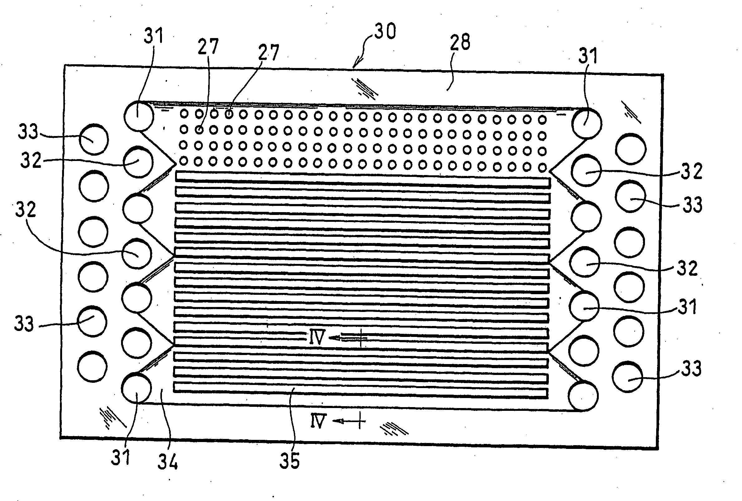
[0108] Firstly, a liquid crystal polymer plate with dimensions of 20 cm.times.32 cm and a thickness of 0.1 mm, reinforced with glass fiber mixed therein, was prepared. In this plate, manifold apertures for an oxidant gas, fuel gas and cooling water, a recess slot for forming the gas flow channels and a large number of through holes were formed, as shown in FIG. 3.

[0109] Next, an artificial graphite powder (mean particle size of about 10 .mu.m) and fibrous graphite (mean diameter of 50 .mu.m, mean length of 0.5 mm) were charged into a 10% hydrogen peroxide aqueous solution, stirred for 10 minutes and then washed well with distilled water. Surface analysis of the thus treated artificial graphite powder and fibrous graphite confirmed the presence of a carbonyl group and a hydroxy group.

[0110] 50 parts by weight of an artificial graphite powder and 38 parts by weight of fibrous graphite, both subjected to the oxidation treatment, was kneaded with 12 parts by weight of a thermosetting ph...


PUM

PropertyMeasurementUnit
Widthaaaaaaaaaa
Densityaaaaaaaaaa
Densityaaaaaaaaaa

Abstract

The present invention relates to a polymer electrolyte fuel cell comprising: an electrolyte membrane-electrode assembly including an anode, a cathode and a polymer electrolyte membrane interposed therebetween; an anode-side conductive separator plate having a gas flow channel for supplying a fuel gas to the anode; and a cathode-side conductive separator plate having a gas flow channel for supplying an oxidant gas to the cathode. A conductive separator plate made of carbon has poor wettability with water. This has posed the disadvantage that variations in performance are induced by nonuniform gas distribution among cells due to the accumulation of product water or humidifying water in the gas flow channel on the surface of the separator plate. The present invention employs a conductive separator plate comprising a conductive carbon having a hydrophilic functional group, at least in a portion of the gas flow channels, thereby preventing water from accumulating in the gas flow channels.

Description

[0001] The present invention relates to fuel cells employing polymer electrolyte which are used in portable power sources, electric vehicle power sources, domestic cogeneration systems and the like, particularly to the improvement of the conductive separator plate thereof.[0002] A fuel cell employing polymer electrolyte generates electric power and heat simultaneously by electrochemically reacting a fuel gas containing hydrogen and an oxidant gas containing oxygen such as air. This fuel cell is basically composed of a polymer electrolyte membrane for selectively transporting hydrogen ions, and a pair of electrodes formed on both sides of the polymer electrolyte membrane, i.e., an anode and a cathode. The electrode usually comprises a catalyst layer which is composed mainly of carbon particles carrying a platinum group metal catalyst and a diffusion layer which has both gas permeability and electronic conductivity and is formed on the outer surface of the catalyst layer.[0003] Gasket...

Claims


Application Information

Patent Timeline
IPC IPC(8): H01M8/02H01M8/04
CPCH01M8/0213H01M8/0226H01M8/026H01M8/0265H01M8/0267H01M8/04007H01M8/04119H01M8/04291Y02E60/50H01M8/2483Y02P70/50H01M8/02
Inventor YAMAMOTO, MASAONIIKURA, JUNJIHASE, NOBUHIROHATOH, KAZUHITOGYOTEN, HISAAKIOHARA, HIDEOKANBARA, TERUHISAYAMAZAKI, TATSUOSUGUO, MASAYA
Owner PANASONIC CORP
Why Eureka
Try Eureka