Coatings, materials, articles, and methods of making thereof

a technology of coatings and materials, applied in the field of coatings, materials and articles, can solve the problems of complex interaction between the microstructure, material failure, and the inability of the current available deposition method to manipulate all the above-described microstructural features, and achieve the effect of improving thermal cycling behavior and durability in thermal cycling tests

Active Publication Date: 2004-11-18
UNIV OF CONNECTICUT +2
View PDF25 Cites 132 Cited by
  • Summary
  • Abstract
  • Description
  • Claims
  • Application Information

AI Technical Summary

Benefits of technology

[0045] In the case of complex compounds such as a mixed oxide ceramic, the reagents are weighed according to the desired stoichiometry of the final compound, i.e., mixed oxide, and then added and mixed with the solution. The precursor solution may be heated and stirred to dissolve the solid components and homogenize the solution. Reagent grade precursors may be suitable for the manufacture of the coatings, particularly for doped semiconductors or oxide membranes used as electronic components, electrodes or electrolytes. Industrial grade precursors may be preferred for the manufacture of structural thick coatings or bulk materials due to the low cost of the starting chemicals. For the fabrication of composite or graded coatings, two or more different precursor solutions may be prepared, and stored in individual containers. The precursor solutions may then be combined prior to spraying or atomized in separate nozzles and sprayed simultaneously or sequentially.
[0046] The precursor solution is delivered to a liquid injector, preferably an atomizing injector nozzle or a piezo electric crystal induced liquid injector. In a one embodiment the precursor solution is atomized into micrometer sized droplets in the atomizing injector nozzle and injected into the thermal spray flame, primarily into the hot zone of the thermal spray flame. In another embodiment, precursor solution is introduced to the thermal spray flame by a piezo electric crystal induced liquid injector which produces large (greater than about 50 micrometers) droplets of low velocity. The majority of the large droplets have sufficient momentum to be carried into the hot zone of the thermal spray flame. The precursor solution may be injected into the thermal spray flame internally or externally, radially or coaxially. When the precursor solution is injected radially, the injector nozzle may be oriented at an angle of about 45.degree. to about 90.degree. relative to the axis of the flame. Preferably the injector nozzle is oriented at about 90.degree. relative to the flame axis. The injection parameters may impact the porosity of the deposited material and the presence or absence of vertical cracks. Multiple radial injectors may be used forming composite or graded materials or increasing deposition efficiency.
[0048] Useful thermal spray methods include all known types of thermal spray. Preferably plasma spray is employed. When plasma spray is the thermal spray method, the porosity and the generation of vertical cracks can be impacted by the argon flowrate. In the case of porosity, a low degree of porosity may be produced using a low argon flow rate. The lower argon flow rate results in a higher temperature plasma flame. In the case of vertical cracking, a high argon flow rate may increase the spacing between the vertical cracks. The high argon flow rate results in a lower temperature flame. Parameters of other types of thermal spray may be similarly modified to achieve similar effects.
[0051] In some embodiment the deposited material comprises fine layers of porosity and unmelted particles called inter pass boundaries. Inter pass boundaries reduce thermal conductivity. The inter pass boundaries have a thickness of about 0.1 to about 2 micrometers and in some embodiments a thickness of about 0.5 to about 2 micrometers. The porosity of the inter pass boundary may effect the overall thermal conductivity of the deposited material. The porosity of the inter pass boundary is about 20 to about 95 volume percent, preferably about 20 to about 75 volume percent, more preferably about 20 to about 50 volume percent, based on the total volume of the inter pass boundary. The inter pass boundaries may exhibit a layered spacing of about 1 to about 10 micrometers. The inter pass boundaries may be continuous or discontinuous. In some embodiments there are no inter pass boundaries within about 50 micrometers of the substrate / coating interface. The absence of inter pass boundaries within 50 micrometers of the substrate / coating interface can enhance coating longevity when subjected to thermal cycling. FIG. 1 shows inter pass boundaries 40.
[0064] One embodiment is a Y.sub.2O.sub.3-stabilized ZrO.sub.2 (YSZ) thermal barrier coating (TBC) having the unique microstructural features illustrated in FIG. 2C. FIG. 2 is a schematic illustrating substrates 12 with conventional powdered feedstock plasma sprayed coating 13, (2B), an EB-PVD-deposited coating 11 (2A), and a solution plasma spray-deposited coating 14 (2C). The microstructural features of the solution plasma spray-deposited coating 14 include fine splats, vertical cracks 17, three-dimensional micrometer size porosity 16 and nanometer size porosity 15. The vertical cracking in the solution plasma spray-deposited coating can provide relief from cyclical thermal stress. The existence of micrometer size porosity and nanometer size porosity (i.e., duplex porosity) in the solution plasma spray-deposited coating can result in reduced thermal conductivity and thereby improve thermal insulation properties as well as enhance thermal stress tolerance. The fine splats in the solution plasma spray-deposited coatings can increase coating integrity and decrease unfavorable cracking (especially lateral cracking) compared to a conventionally sprayed coating 13 that has a lamellar structure consisting of many large (i.e., 100 micrometers or greater) inherent splat boundaries as shown in FIG. 2B. The unique coating structure is clearly exhibited in the scanning electron microscope (SEM) cross-section in FIG. 3.
[0068] The thermal barrier coatings produced by solution plasma spray exhibit improved thermal cycling behavior even at coating thicknesses over 12 mils (305 micrometers), FIG. 8. Typically, the thicker the coating, the fewer cycles it can withstand. A 305 micrometer thick powdered feedstock plasma sprayed 7YSZ coating can withstand 391 thermal cycles, while a 305 micrometer solution plasma spray deposited 7YSZ coating can withstand 1018 cycles. Further, 508 micrometer and 635 micrometer solution plasma spray deposited coatings can withstand over 650 thermal cycles. Even a 1016 micrometer solution plasma spray deposited coating can withstand 555 thermal cycles.

Problems solved by technology

Thus it is clear that there is a complex interaction between the microstructure, composition, end use and the method of making the coating or material.
The size of the splat boundary is related to the size of the splat and large splat boundaries may result in lateral cracking, potentially causing material failure.
None of the currently available methods of deposition is capable of manipulating all the above-described microstructural features.

Method used


Image

  • Coatings, materials, articles, and methods of making thereof
  • Coatings, materials, articles, and methods of making thereof
  • Coatings, materials, articles, and methods of making thereof

Examples


example 1

ZrO.sub.2+7 wt % Y.sub.2O.sub.3 (7YSZ) Thermal Barrier Coating

[0077] The precursor solution was prepared as follows. Zirconium acetate was dissolved in a weak organic acid and then mixed with distilled water to form a solution having a pH of 3-5. The Zr solution was mixed with yttrium nitrate to form a precursor solution. Multiple coatings were formed by deposition of the precursor solution according to the parameters in Table 2.

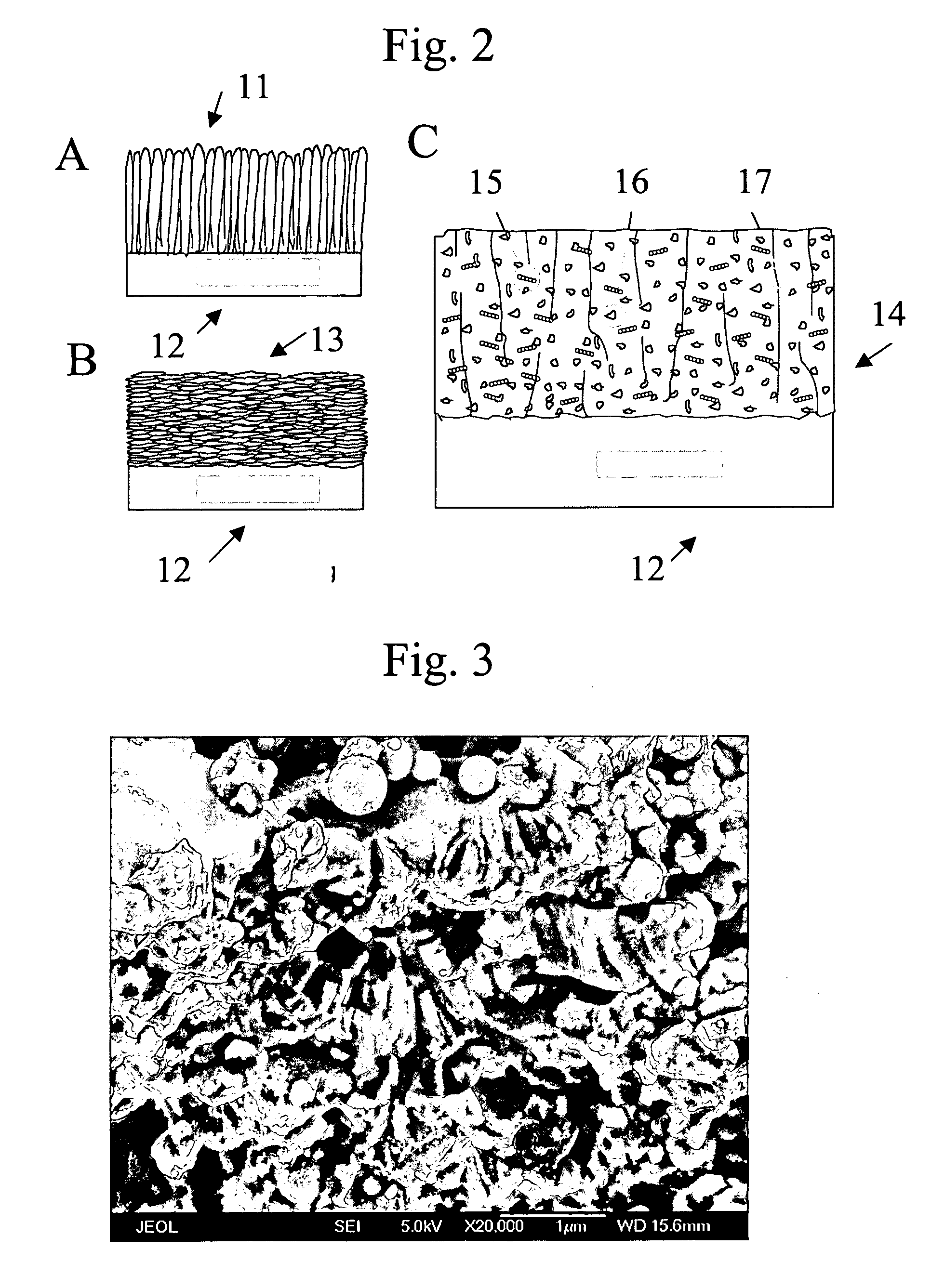
[0078] The solution plasma spray deposited 7YSZ had a porosity of about 15 volume % to about 30 volume % of the total volume of the coating and a thickness of about 300 micrometers to as much as 3,000 micrometers. The 7YSZ coating was well bonded to the substrate, contained fine splats, and contained some spaced vertical cracks as well as micrometer and nanometer-sized porosity. FIG. 3 shows the splats and vertical cracking. Moreover, the 7YSZ coating structure was verified to be stable in retaining nanometer grain size and reducing sintering during long-ter...

example 2

ZrO.sub.2+20 wt % Y.sub.2O.sub.3 (20YSZ) Electrolyte Layer

[0080] The precursor solution was prepared by dissolving zirconium acetate in acetic acid and then mixing with distilled water with a pH of 3-5. Then yttrium nitrate was mixed with the solution to form the precursor solution. Multiple coatings were formed by deposition of the precursor solution according to the parameters in Table 2.

[0081] The solution plasma spray deposited 20YSZ had a porosity of less than about 2 volume % of the total volume of the coating (FIG. 6A). The coating was crack-free and adherent to the substrate when its thickness was below 100 micrometers. However, vertical cracks and coating exfoliation occurred in coatings having a thickness more than 200 micrometers. The coating comprised cubic-ZrO.sub.2.

[0082] A stainless steel strip was coated with a solution plasma spray-applied 20YSZ coating, then bent into 90.degree. angles. As shown in FIG. 10, no spallation in the deformed area was found with the exce...

example 3

Al.sub.2O.sub.3 Coating

[0083] The precursor solution was prepared by dissolving aluminum nitrate in distilled water to form a 1.0 mole precursor solution. Coatings were formed by deposition of the precursor solution according to the parameters in Table 2.


PUM

PropertyMeasurementUnit
temperatureaaaaaaaaaa
diameteraaaaaaaaaa

Abstract

A thermal spray process comprises injecting precursor solution droplets into the hot zone of the thermal spray flame. Also described are materials resulting from the process.

Description

[0001] This application claims priority to Provisional Application Serial No. 60 / 439,288 filed on Jan. 10, 2003, which incorporated by reference herein.[0003] There is a wide variety of methods for forming a coating or deposited material. Methods include chemical vapor deposition, physical vapor deposition, laser assisted pyrolysis deposition, electron-beam physical vapor deposition and thermal spray. The coating or material produced by these methods can vary significantly in microstructure from method to method. The microstructure of the coating or material, as well as its composition, has a significant impact the physical and mechanical properties, as well as the end use. Thus it is clear that there is a complex interaction between the microstructure, composition, end use and the method of making the coating or material.[0004] Microstructure, as used herein, refers to the structure of the material or coating on a microscopic level. Components of microstructure include the phases p...

Claims


Application Information

Patent Timeline
Patent Type & Authority Applications(United States)
IPC IPC(8): C04B35/50C23C4/12H01M8/12
CPCB82Y30/00Y10T428/268C04B35/486C04B35/50C04B2235/3206C04B2235/3213C04B2235/3225C04B2235/3227C04B2235/3229C04B2235/3286C04B2235/449C04B2235/77C04B2235/781C23C4/121H01M4/9025H01M4/9033H01M8/1253H01M2008/1293Y02E60/521Y02E60/525Y02T50/67Y10T428/25Y10T428/26C04B35/01C23C4/123Y10T428/249986Y10T428/249953Y10T428/249967Y10T428/24997Y02E60/50Y02P70/50Y02T50/60
Inventor GELL, MAURICEMA, XINQINGJORDAN, ERICPADTURE, NITIN P.XIE, LIANGDEXIAO, DANNYDECARMINE, ANTHONY
Owner UNIV OF CONNECTICUT
Why Eureka
Try Eureka