Alkaline earth aluminate phosphor for a cold cathode fluorescent lamp and cold cathode fluorescent lamp

a fluorescent lamp and alkaline earth technology, applied in the direction of discharge tube/lamp details, discharge tube luminescent compositions, discharge tube luminescent screens, etc., can solve the problems of light flux reduction, light deterioration, and light deterioration, and achieve low heat deterioration, high emission intensity, and low cost

Active Publication Date: 2005-02-03
MITSUBISHI CHEM CORP
View PDF6 Cites 8 Cited by
  • Summary
  • Abstract
  • Description
  • Claims
  • Application Information

AI Technical Summary

Benefits of technology

[0019] Under these circumstances, the present invention has been made to provide a Eu2+ and Mn2+-co-activated alkaline earth aluminate phosphor for a cold cathode fluorescent lamp, which exhibits high emission intensity in a green wavelength region as compared with a blue wavelength region when irradiated with ultraviolet r...

Problems solved by technology

However, the Mn2+-activated zinc silicate type phosphor and the Mn2+-activated magnesium gallate type phosphor do not exhibit green emission with high luminance which can be practically used by ultraviolet rays by discharge of mercury, and if they are used as a fluorescent layer of a fluorescent lamp, the lamp luminous flux decreases with time due to reaction with mercury or ion impact, and thus they are not practically used yet.
This phosphor has been often used practically as a phosphor of a fluorescent lamp for lighting or for copying machine, however, further development has been required since degree of heat deterioration of the phosphor is slightly high.
However, this phosphor tends to deteriorate in a baking step when a fluorescent layer is formed, and the luminous flux tends to decrease with time.
This phosphor exhibits emission having an emission spectrum having a first emission peak in a wavelength region of from 445 to 455 nm and a second emission peak in a wavelength region of from 510 to 520 nm, however, the intensity of the second emission peak is low as compared with the first emission peak, such being insufficient as a g...

Method used


Image

  • Alkaline earth aluminate phosphor for a cold cathode fluorescent lamp and cold cathode fluorescent lamp
  • Alkaline earth aluminate phosphor for a cold cathode fluorescent lamp and cold cathode fluorescent lamp
  • Alkaline earth aluminate phosphor for a cold cathode fluorescent lamp and cold cathode fluorescent lamp

Examples


example 1

[0075]

BaCO3 0.85 molEu2O3 0.075 mol3MgCO3.Mg(OH)20.1625 molMnO2 0.35 molAl2O3 (α type)  5.0 molAlF3 0.030 mol

[0076] The above materials as the phosphor materials were thoroughly mixed and filled in a crucible, a block of graphite was put on the phosphor materials, and a cover was put, followed by baking in a nitrogen and hydrogen atmosphere containing water vapor at a maximum temperature of 1,450° C. over a period of 24 hours including the temperature raising time.

[0077] Then, the baked powder was dispersed, washed, dried and sieved to obtain a Eu2+ and Mn2+-co-activated barium magnesium aluminate phosphor of Example 1 having a compositional formula of (Ba0.85Eu0.15) (Mg0.65Mn0.35).5Al2O3 and having an average particle size of 6.7 μm as measured by a Fisher Subsieve Sizer. Here, AlF3 is a flux which is commonly used for production of a phosphor.

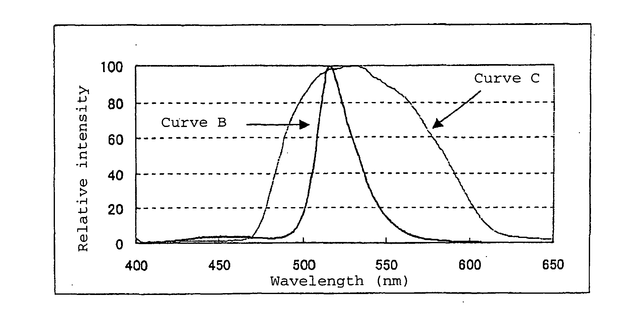
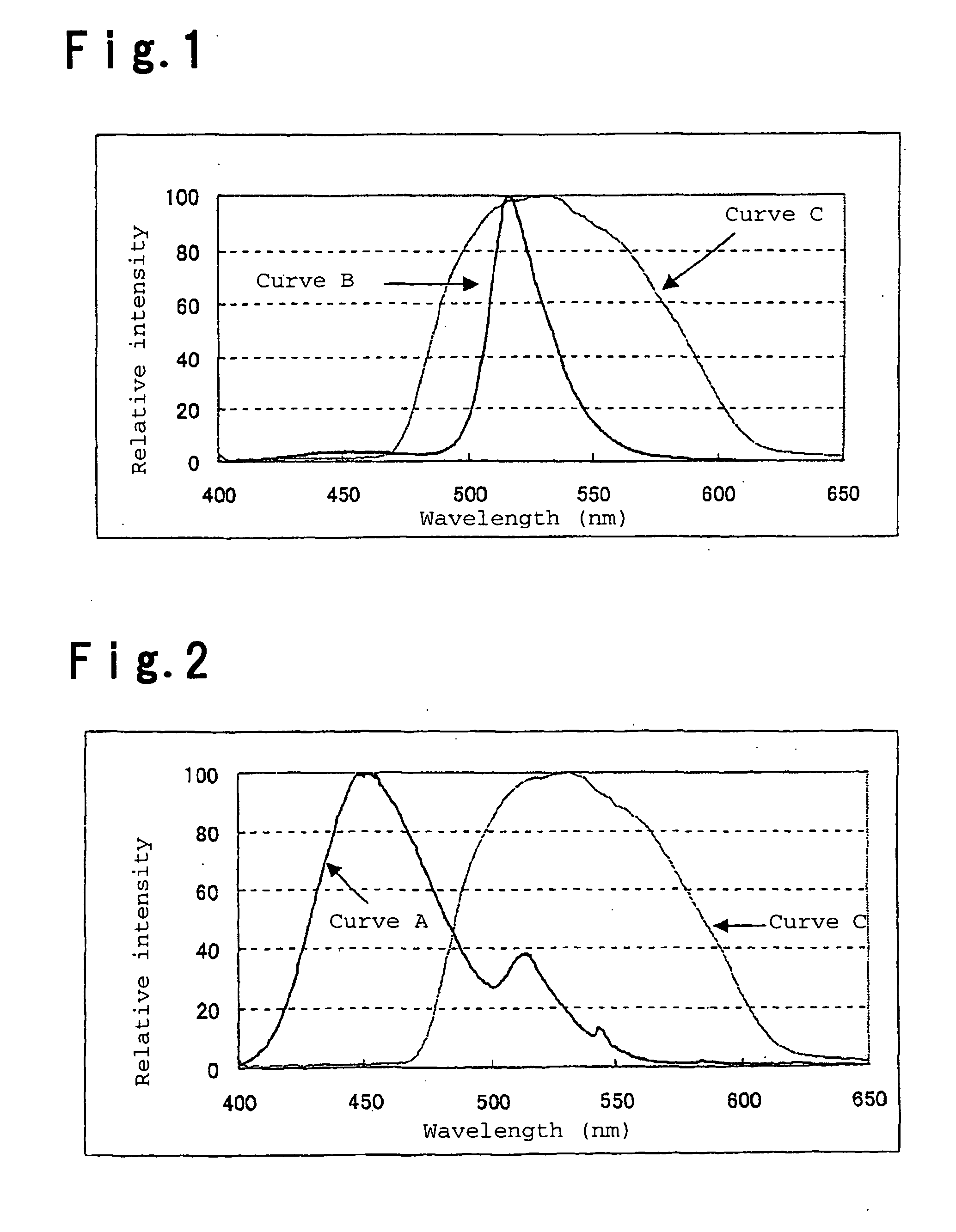
[0078] The emission spectrum of the phosphor of Example 1 had emission peaks at 452 nm and 516 nm, the intensity ratio of the two peaks (P...

example 2

[0083]

BaCO3 0.855 molEu2O30.0475 mol3MgCO3.Mg(OH)2 0.15 molMnO2  0.4 molAl2O3 (α type) 4.75 molAlF3 0.030 mol

[0084] The same operation as in Example 1 was carried out except that the above materials were used as the phosphor materials to obtain a Eu2+ and Mn2+-co-activated barium magnesium aluminate phosphor of Example 2 having a compositional formula of 0.95(Ba0.9Eu0.1) (Mg0.6Mn0.4).4.75Al2O3 and having an average particle size of 7.0 μm as measured by a Fisher Subsieve Sizer.

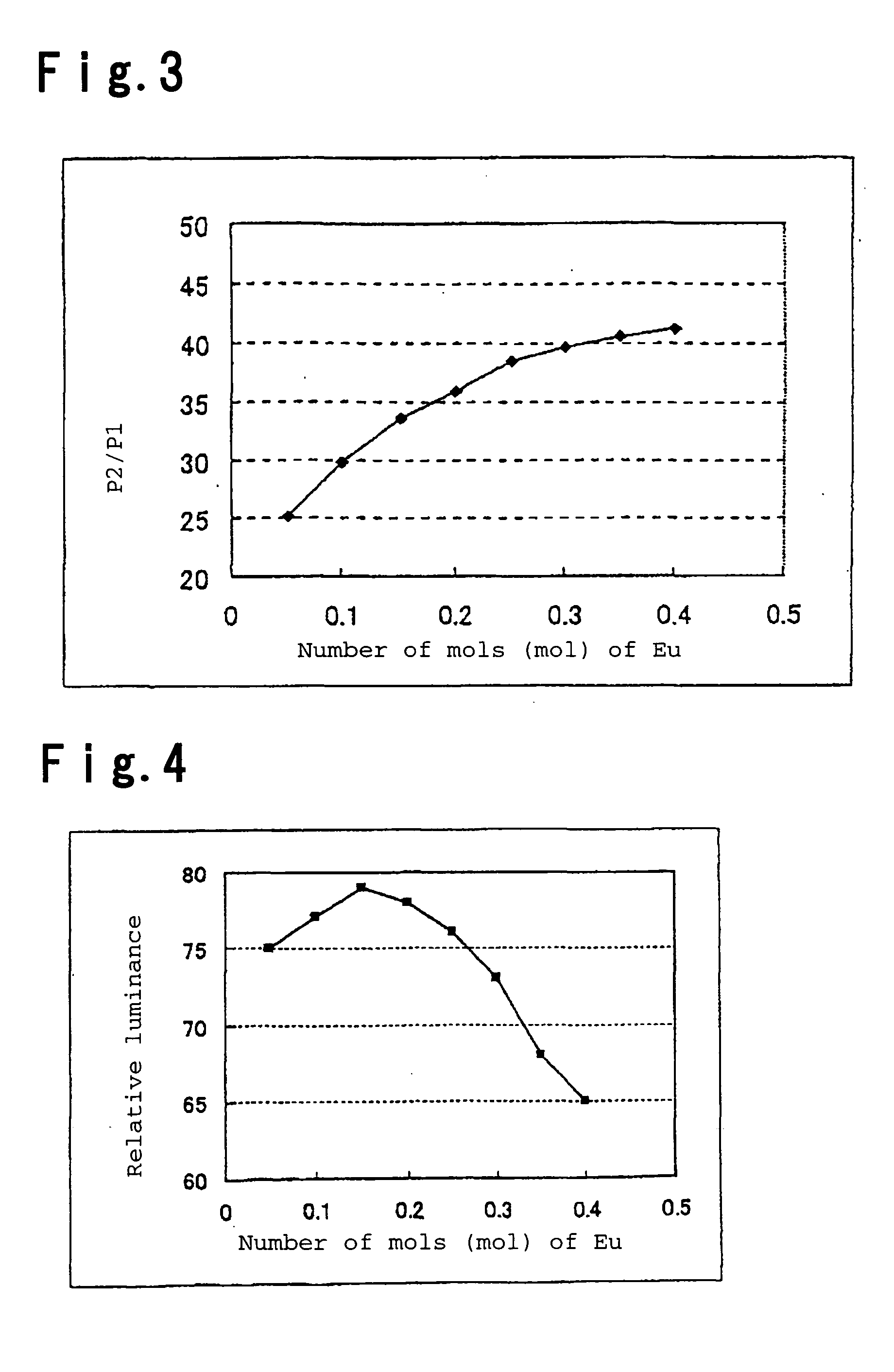
[0085] The emission spectrum of the phosphor of Example 2 had emission peaks at 450 nm and 516 nm, the intensity ratio of the two peaks (P2 / P1) was 50.2 wherein P1 is the intensity of the emission peak at 450 nm and P2 is the intensity of the emission peak at 516 nm, and the emission color was practical as a green phosphor with luminescent chromaticity by CIE color system of x=0.141 and y=0.724.

[0086] The phosphor of Example 2 was irradiated with ultraviolet rays of 253.7 nm and the emission luminance was me...

example 3

[0090]

BaCO3 0.84 molEu2O30.105 mol3MgCO3.Mg(OH)2 0.2 molMnO2 0.2 molAl2O3 (α type) 5.25 molAlF30.020 mol

[0091] The same operation as in Example 1 was carried out except that the above materials were used as the phosphor materials to obtain a Eu2+ and Mn2+-co-activated barium magnesium aluminate phosphor of Example 3 having a compositional formula of 1.05(Ba0.8Eu0.2)(Mg0.8Mn0.2) 5.25Al2O3 and having an average particle size of 7.0 μas measured by a Fisher Subsieve Sizer.

[0092] The emission spectrum of the phosphor of Example 3 had emission peaks at 454 nm and 515 nm, the intensity ratio of the two peaks (P2 / P1) was 14.5 wherein P1 is the intensity of the emission peak at 454 nm and P2 is the intensity of the emission peak at 515 nm, the luminescent chromaticity was x=0.140 and y=0.634, and the emission color was practical as a green phosphor.

[0093] The phosphor of Example 3 was irradiated with ultraviolet rays of 253.7 nm and the emission luminance was measured, whereupon it was 99...


PUM


Abstract

An alkaline earth aluminate phosphor for a cold cathode fluorescent lamp, which is represented by the compositional formula a (P1-xEux)O.(Q1-yMny)O.bAl2O3 and which is characterized by emitting light when irradiated with ultraviolet rays having a wavelength of from 180 to 300 nm (provided that in the above formula, P represents at least one alkaline earth metal element selected from Ba, Sr and Ca, Q represents at least one bivalent metal element selected from Mg and Zn, and a, b, x and y represent numbers which satisfy 0.8≦a≦1.2, 4.5≦b≦5.5, 0.05≦x≦0.25 and 0.2≦y≦0.4, respectively).

Description

BACKGROUND OF THE INVENTION [0001] 1. Field of the Invention [0002] The present invention relates to an alkaline earth aluminate phosphor for a cold cathode fluorescent lamp, which exhibits green emission with high luminance with emission in a blue wavelength region suppressed by ultraviolet rays having a wavelength of from 180 to 300 nm, with little decrease in emission luminance due to heat (heat deterioration), and a cold cathode fluorescent lamp which employs the above phosphor as a fluorescent layer, which has a high luminous flux and which realizes a beautiful display screen with a wide color reproduction range when used for a back light of e.g. a liquid crystal display. [0003] 2. Discussion of Background [0004] In recent years, diffusion of flat panel displays (FPD) represented by liquid crystal displays (LCD) and plasma displays (PDP) is remarkable. FPD is classified into so-called light emitting displays such as PDP in which picture elements constituting an image on the pan...

Claims


Application Information

Patent Timeline
IPC IPC(8): C09K11/77C09K11/64C09K11/80H01J1/62H01J61/44
CPCH01J61/44C09K11/7734H01J1/63C09K11/645H01J2211/42
Inventor OTSUKA, REIJI
Owner MITSUBISHI CHEM CORP
Why Eureka
Try Eureka