
Catalyst composition and deposition method

a technology of catalyst composition and deposition method, which is applied in the direction of physical/chemical process catalyst, organic compound/hydride/coordination complex catalyst, etc., can solve the problems of limited shielding effectiveness, peeling of coatings, and often difficult deposition of metal layers of uniform thickness on substrates by workers. achieve the effect of increasing the effective area of catalys

Active Publication Date: 2005-02-03
ROHM & HAAS ELECTRONICS MATERIALS LLC
View PDF32 Cites 24 Cited by
  • Summary
  • Abstract
  • Description
  • Claims
  • Application Information

AI Technical Summary

Benefits of technology

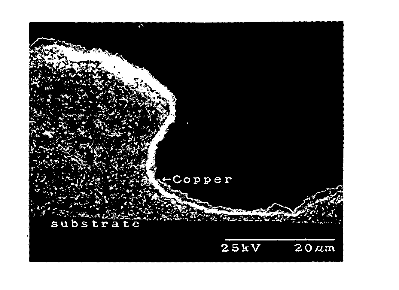
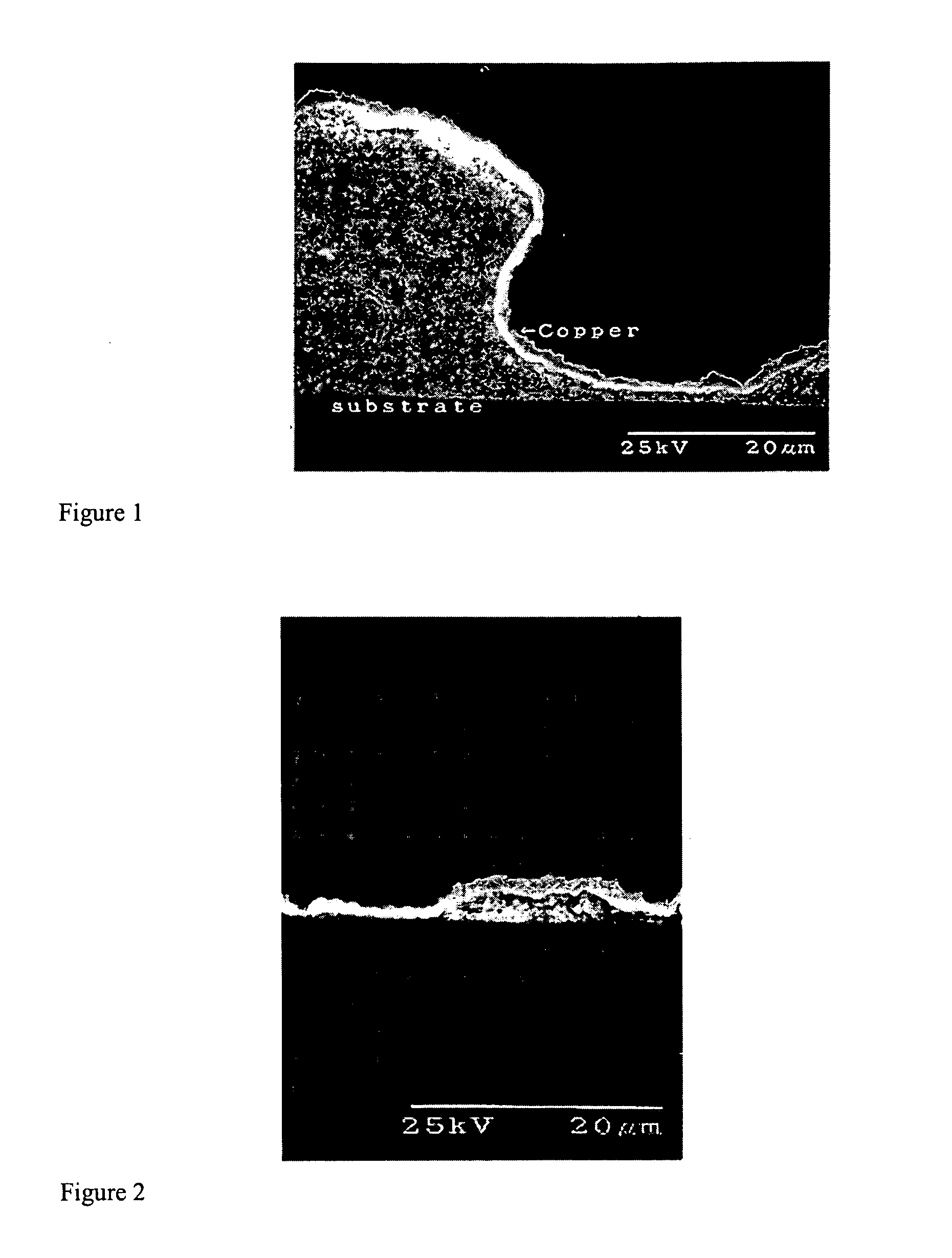
[0014] Compositions of the invention include a catalyst, one or more carriers having an average particle size of from 5 nm to 900 nm, and one or more water-soluble or water-dispersible organic compounds. The compositions of the present invention do not employ organic solvents as the water-soluble or water-dispersible organic compounds provide sufficient means of adhesion for the compositions to a non-conductive substrate. Accordingly, roughening a non-conductive surface with a solvent swell is avoided when using the present compositions, thus eliminating many potentially hazardous compounds from the compositions. The nano-sized carrier particles, on which the catalysts are coated, increase the effective area of the catalysts, thus permitting a continuous catalytic layer to be placed on a substrate. The catalytic layer permits electroless metals to nucleate and grow through the catalytic layer to the substrate permitting the substrate to come into electrical contact with deposited metal.

Problems solved by technology

Workers often have difficulty in depositing metal layers of uniform thickness on substrates with crevices or holes using electrolytic methods of plating.
EMI radiation may interfere with other devices and has been known to cause such diverse problems as interference with police mobile radios, communication systems, scientific test equipment and cardiac pacemakers.
Such methods have suffered from a number of deficiencies such as macro or microscopic cracking, peeling of coatings, limited shielding effectiveness, oxidation of metals in the coatings, distortion of thermoplastic substrates, and expensive application equipment.
While the foregoing electroless catalyst and method was superior to many of the earlier methods employed to address the problem of EMI shielding, the electroless coating process was not selective.
Where aesthetics are important in the marketing of electronic components, an exterior metal coated housing for the electronic component is undesirable.
This is a time consuming and wasteful step, especially where housings are most often molded in a desired color.
Solvation of the substrate permits penetration of the substrate by the catalyst, however, such solvation may lead to surface defects in the substrate.
The irregular surface may result in a non-uniform metal layer, which may result in non-uniform shielding.
Additionally, using solvent swells present a hazard to workers and the environment because many solvents are toxic, carcinogenic and require special and costly disposal procedures.

Method used


Image

  • Catalyst composition and deposition method
  • Catalyst composition and deposition method
  • Catalyst composition and deposition method

Examples


example 1

A Catalytic Primer of the Invention

[0068] A stock solution of hydrated silver hydroxide was prepared by mixing 50 gm of silver nitrate (AgNO3) with 10 gm of sodium hydroxide (NaOH) at room temperature (18° C. to 20° C.), which formed a brown precipitate of hydrated silver oxide. The precipitate was allowed to settle and was then washed with a sufficient amount of deionized water to bring the pH to 9.

[0069] 0.1 gm of the hydrated silver oxide was then added to an aqueous composition containing 2.5 gm of barium sulfate (BaSO4) having an average particle size of 300 nm, 0.25 gm of iron oxide (Fe2O3) having an average particle size of 550 nm and 8.75 gm of water. The solids were dispersed in the water under high-shear agitation using a stirring apparatus. 1.2 gm of Bisphenol-A epoxy resin with an average molecular weight of 1300 equivalent weights was then added and mixed under low-shear using a stirring apparatus until a uniform slurry was formed.

[0070] A solution of 0.33 gm of an a...

example 2

A Catalytic Primer of the Invention

[0071] 0.045 gm of the stock hydrated silver oxide from Example 1 was added to an aqueous composition containing 2.5 gm of barium sulfate (BaSO4) having an average particle size of 300 nm, 0.15 gm of iron oxide (Fe2O3) having an average particle size of 550 nm, 0.5 gm di(ethylene glycol) butyl ether, and 9 gm of water. The solids were dispersed in the water using high-shear agitation. 0.8 gm of an aqueous-dispersed polyurethane resin containing hydrophobic segments in its backbone and 0.01 gm of an alkoxysilane cross-linker were added to the slurry using low-shear agitation. The ratio of inert filler to metal catalyst was 65 to 1.

example 3

A Catalytic Primer of the Invention

[0072] 0.045 gm of the stock hydrated silver oxide from Example 1 was added to an aqueous composition containing 3.6 gm of barium sulfate (BaSO4) having an average particle size of 300 nm, 0.25 gm of iron oxide (Fe2O3) having an average particle size of 550 nm, 0.5 gm di(ethylene glycol) butyl ether, and 6 gm of water. The solids were dispersed in the water using high-shear agitation. 0.8 gm of an aqueous-dispersed polyurethane resin containing hydrophobic segments in its backbone was added to the slurry using low-shear agitation. The ratio of inert filler to metal catalyst was 94 to 1.


PUM

PropertyMeasurementUnit
particle sizesaaaaaaaaaa
surface resistanceaaaaaaaaaa
thicknessaaaaaaaaaa

Abstract

Compositions and methods for depositing one or more metal or metal alloy films on substrates. The compositions contain a catalyst, one or more carrier particles and one or more water-soluble or water-dispersible organic compounds. Metal or metal alloys may be deposited on the substrates by electroless or electrolytic deposition.

Description

BACKGROUND OF THE INVENTION [0001] The present invention is directed to an aqueous catalyst composition and method of depositing an ultra-thin metal or metal alloy layer on a substrate. More specifically, the present invention is directed to an aqueous catalyst composition and method of depositing an ultra-thin metal or metal alloy layer on a substrate where the aqueous catalyst has high surface area particles. [0002] Many industries where workers desire to coat or form one or more metal or metal alloy layers on substrates employ catalysts. Such catalysts are employed in electroless deposition of metal or metal alloys. Electroless deposition or plating is based on the presence of a chemical reducing agent being added to the deposition bath. Such chemicals supply electrons to substrate metals, which transmit the electrons to the positively charged metal ions in the bath reducing these ions to metal in the same manner in which electric current reduces metal ions to metals in electroly...

Claims


Application Information

Patent Timeline
Patent Type & Authority Applications(United States)
IPC IPC(8): B01J23/38B01J23/66B01J23/70B01J23/72B01J23/89B01J23/58B01J29/76B01J31/12B01J35/00B01J37/02B01J37/16C23C18/12C23C18/16C23C18/18C23C18/20C23C18/30C25D5/54C25D7/06H01B5/14
CPCB01J23/38Y10T428/265B01J23/70B01J23/72B01J23/8946B01J35/0013B01J35/0033B01J37/0219B01J37/0228B01J37/16C23C18/1608C23C18/1879C23C18/206C23C18/30B01J23/66B01J35/23B01J35/33B01J31/12B01J37/02
Inventor LEVEY, PETER R.BRESE, NATHANIEL E.
Owner ROHM & HAAS ELECTRONICS MATERIALS LLC
Learn More