Endovascular implant for the injection of an active substance into the media of a blood vessel

Inactive Publication Date: 2005-02-03
BIOTRONIK
View PDF11 Cites 69 Cited by
  • Summary
  • Abstract
  • Description
  • Claims
  • Application Information

AI Technical Summary

Benefits of technology

[0015] The above-indicated configuration of the implant according to the invention makes it possible for the active substances to be eluted directly at the specific location of the action of the active substances, namely the media. Concomitantly therewith the applied amount of active substance can be substantially reduced so that the production costs of the LDD-implant can be markedly reduced and alocal side-effects are very substantially excluded.
[0021] It is further preferred that a plurality of active substances are provided in the active substance deposit and the liberation thereof takes place in a stepwise manner. That can be effected for example in such a way that a plurality of layers of biodegradable drug carriers with various active substances are introduced in layer-wise fashion into the active substance deposit. The layers are successively broken down from the outside inwardly, and accordingly successively liberate the various active substances. It is also possible for one or more separating layers—again comprising a biodegradable material—to be introduced into the active substance deposit. The separating layers serve to separate the various active substances and are broken down in succession. A time-staged process of that kind makes it possible to effectively influence the underlying mechanisms of restenosis. Thus for example the initial mechanisms of restenosis can be specifically and targetedly combated by anti-proliferative substances and at a later time, by the application of anti-inflammatory substances and the like, cell migration can be prevented.
[0022] Preferably, the regions of the surface of the implant, which are outside the microdevice, are also covered with a layer of a biodegradable material. More specifically, it has been found that bioactive surfaces of that kind markedly reduce the restenosis rate. Preferred materials are hyaluronic acid polymer, polylactides and heparin.
[0023] If the layer terminates flush in the peripheral direction with a tip of the microcannula of the microdevice or if it is indeed completely covered then the structure on the one hand is initially protected from mechanical damage upon being introduced into the body while on the other hand penetration of the microcannula into the vessel wall can be controlled, in respect of time. The microcannulae slowly penetrate through the intima into the media, due to the gradual breakdown of the layer. That slow penetration prevents damage to the vessel wall, which damage in turn could be the starting point for restenosis processes. In order to prevent premature liberation of the active substance, the liberation behaviour of the deposited active substance must be suitably matched by virtue of the choice of the biodegradable drug carrier or a cover layer. Hyaluronic acid is particularly suitable for coating the surface in the regions outside the microstructure. A breakdown behaviour on the part of the hyaluronic acid can be established by specific and targeted cross-linking in the desired manner. Therefore, that material is also suitable as the cover layer and the drug carrier. The production of cross-linked hyaluronic acid coatings and the influencing of degradation behaviour is known in principle from the state of the art. In general terms, the degradation time increases with an increasing degree of polymerisation and / or degree of cross-linking of the carrier. An elution characteristic which applies in respect of the embedded active substance depends on the degree of polymerisation and cross-linking, besides depending on diffusion processes. In general elution is increased in length, with an increasing degradation time.
[0025] In a further variant of the invention, the base body of the implant, in particular the stent, is also formed from a biodegradable magnesium alloy. Complete breakdown of the stent provides for long-term elimination of the factors which possibly trigger off restenosis.

Problems solved by technology

It will be noted however that expansion of the blood vessel gives rise to injuries (tears, so-called dissections) in the vessel wall, which admittedly predominantly heal without any problem but which in about a third of cases, due to triggered cell growth, result in growths (proliferation) which ultimately result in renewed vessel constriction (restenosis).
The expansion effect also does not eliminate the physiological causes of the stenosis, that is to say the changes in the vessel wall.
A further cause of restenosis is the elasticity of the expanded blood vessel.
The use of stents admittedly makes it possible to achieve an optimum vessel cross-section, but the use of stents also results in very minor damage which can induce proliferation and thus ultimately can trigger restenosis.
Under the influence of various growth factors the smooth muscle cells produce a cover layer of matrix proteins (elastin, collagen, proteoglycans) whose uncontrolled growth can gradually result in constriction of the lumen.
Systematically medicinal therapy involvements provide inter alia for the oral administration of calcium antagonists, ACE-inhibitors, anti-coagulants, anti-aggregants, fish oils, anti-proliferative substances, anti-inflammatory substances and serotonin-antagonists, but hitherto, significant reductions in the restenosis rates have not been achieved in that way.
A basic problem in terms of medicinal treatment or prevention of re-stenosis is the in part considerable side-effects of the active substances.
Diffusion of the active substance can however be impeded by generally present plaque, calcification or thickened vessel wall layers.

Method used


Image

  • Endovascular implant for the injection of an active substance into the media of a blood vessel
  • Endovascular implant for the injection of an active substance into the media of a blood vessel
  • Endovascular implant for the injection of an active substance into the media of a blood vessel

Examples


Embodiment Construction

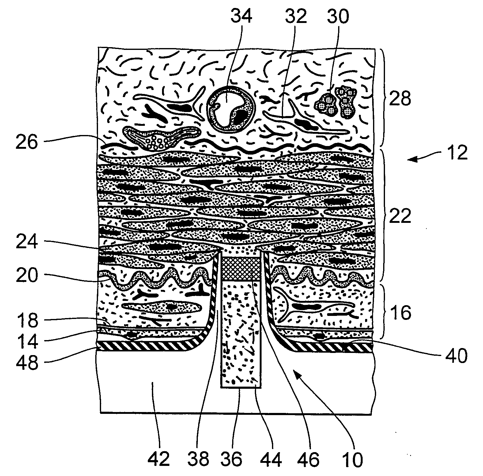
[0035]FIG. 1 diagrammatically shows a view in cross-section through an endovascular implant in the region of a microdevice 10 which has already penetrated into a vessel wall 12 of a muscular artery. The endovascular implant can be in particular a stent. The stent is formed from a biocompatible material, for example nitinol, medical steel, tantalum, platinum-iridium alloys, gold or the like. It is also possible to use a biodegradable magnesium alloy. The design and dimensioning of the stent can be variable to a wide extent. They only have to permit the arrangement or the provision of the microdevices 10 on the outside surface thereof.

[0036] In accordance with prevailing histological teaching, the vessel wall 12 of the artery is divided into three layers. Following the inner endothelium cells 14 which line the vessel wall 12, there extends the region of the so-called intima 16 which is delimited by a basal lamina 18 and an inner elastic membrane 20. The intima 16 is adjoined by the m...


PUM


Abstract

The invention concerns an endovascular implant for the application of an active substance into the media 22 of a blood vessel and two processes for the production thereof. A base body 42 of the implant has at least in portion-wise manner at a surface 40 which is towards the blood vessel, a plurality of microdevices 10 for injection of the active substance. Each microdevice 10 includes on the one hand at least one microcannula 38 which is raised out of the surface 40 of the implant to such an extent that, when the implant bears against a wall 12 of the blood vessel in surface contact, the microcannula penetrates into the media 22 of the blood vessel, and on the other hand at least one active substance deposit 36 which is in communication with at least one microcannula 38.

Description

[0001] The invention concerns an endovascular implant for the application of an active substance into the media of a blood vessel and two processes for the production of such an implant. BACKGROUND OF THE ART [0002] One of the most frequent causes of death in Western Europe and North America is coronary heart disease. According to recent knowledge, in particular inflammatory processes are the driving force behind arteriosclerosis. The process is supposedly initiated by the increased deposit of low-density lipoproteins (LDL-particles) in the intima of the vessel wall. After penetrating into the intima the LDL-particles are chemically modified by oxidants. The modified LDL-particles in turn cause the endothelium cells which line the inner vessel walls to activate the immune system. As a consequence monocytes pass into the intima and mature to macrophages. In conjunction with the T-cells which also enter inflammation mediators such as immune messenger substances and proliferatively act...

Claims


Application Information

Patent Timeline
IPC IPC(8): A61F2/00A61F2/02A61F2/06
CPCA61F2/06A61F2250/0068A61F2250/0067A61F2/2493
Inventor MOMMA, CARSTENBECKER, ANDREASSCHMIEDL, ROBERTHEUBLEIN, BERND
Owner BIOTRONIK
Why Eureka
Try Eureka