Polymer gel hybrid solar cell

a solar cell and polymer gel technology, applied in the field of polymer gel hybrid solar cells, can solve the problems of limiting the nature of components and polymerisation techniques, unable to form many gels in the presence of iodine, and high manufacturing costs of solar cells based on si, and achieves high energy conversion efficiency

Inactive Publication Date: 2005-02-10
SONY DEUT GMBH +1
View PDF9 Cites 57 Cited by
  • Summary
  • Abstract
  • Description
  • Claims
  • Application Information

AI Technical Summary

Benefits of technology

[0006] Therefore it is an object of the present invention to avoid the problems described in relation to polymer gel electrolyte solar cells. It is a further object to pr

Problems solved by technology

Solar cells based on Si are, however, rather expensive to manufacture, even in the amorphous Si version.
However, for these solar cells to become widely used, there are still a number of drawbacks to overcome, namely the use of liquid electrolytes for charge transport.
There are, however, also problems associated with this approach, since for the formation of suitable gels, so

Method used


Image

  • Polymer gel hybrid solar cell
  • Polymer gel hybrid solar cell
  • Polymer gel hybrid solar cell

Examples


example 1

[0052] In one example, polyethylene oxide [PEO, Mw 400.000] was used in ethylene carbonate [EC] / propylene carbonate [PC] mixture filled with lithium iodide / iodine [LiI / I2] and an inert Li salt. In PEO polymer gel electrolyte, the solid polymer matrix of PEO provides dimensional stability to the electrolyte, while the high permittivity of the solvents PC and EC enables extensive dissociation of the Li salts to take place. The low viscosity of PC and EC provides an ionic environment that facilitates high ionic mobility. Such polymer gel electrolytes exhibits high ionic conductivities in excess of 103 S / cm.

example 2

[0053] Solar Cell Preparation

[0054] Blocking Layer

[0055] Made by spray pyrolysis: spraying with an atomiser an aerosol dispersion of an organic precursor titanium acetylacetonate (TAA, Aldrich) in ethanol (concentration of 0.2 M) onto structured FTO coated glass substrates (at 450° C.) (Geomatic). To get a thin, amorphous, compact layer of TiO2 (about 30 nm), films are tempered at 500° C. in air for 1 hour.

[0056] Nanocrystalline TiO2 Electrode+Dye Layer

[0057] Porous TiO2 layers are made by screen printing of a paste containing TiO2 particle of 10 nm or 20 nm diameter respectively (Solaronix Company) on top of the blocking TiO2 layer (thickness depends on mesh size of screens). To get rid of the organic solvents and surfacatants, and to enable a contact between TiO2 particles, porous TiO2 layers are heated up to 85° C. for 30 minutes in a first step and sintered at 450° C. for ½ hour. After cooling down to 80° C., films are placed into a dye solution in ethanol (5×10⁻⁴ M) and sta...

example 3

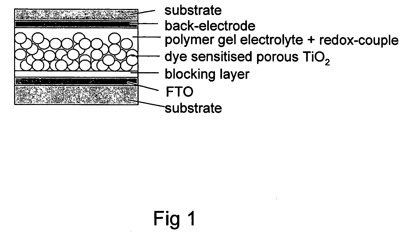
[0069] The photovoltaic cell is fabricated by drop casting the ready made gel electrolyte on top of the dye-sensitised porous TiO2 coated electrode, and sandwiched with a platinum back-electrode.

[0070] The layer thickness of the nanocrystalline TiO2, is varied in the range of 2 to 20 μm, containing particles of 10 or 20 nm in diameter. The illuminated area of the cell is ca. 0.5-0.6 cm2. As sensitizer dye cis-di(thiocyanato) bis (2,2′-bipyridyl-4,4′-dicarboxylate) ruthenium (II) tetrabutylammonium (Ru(bpy)TBA) is used.

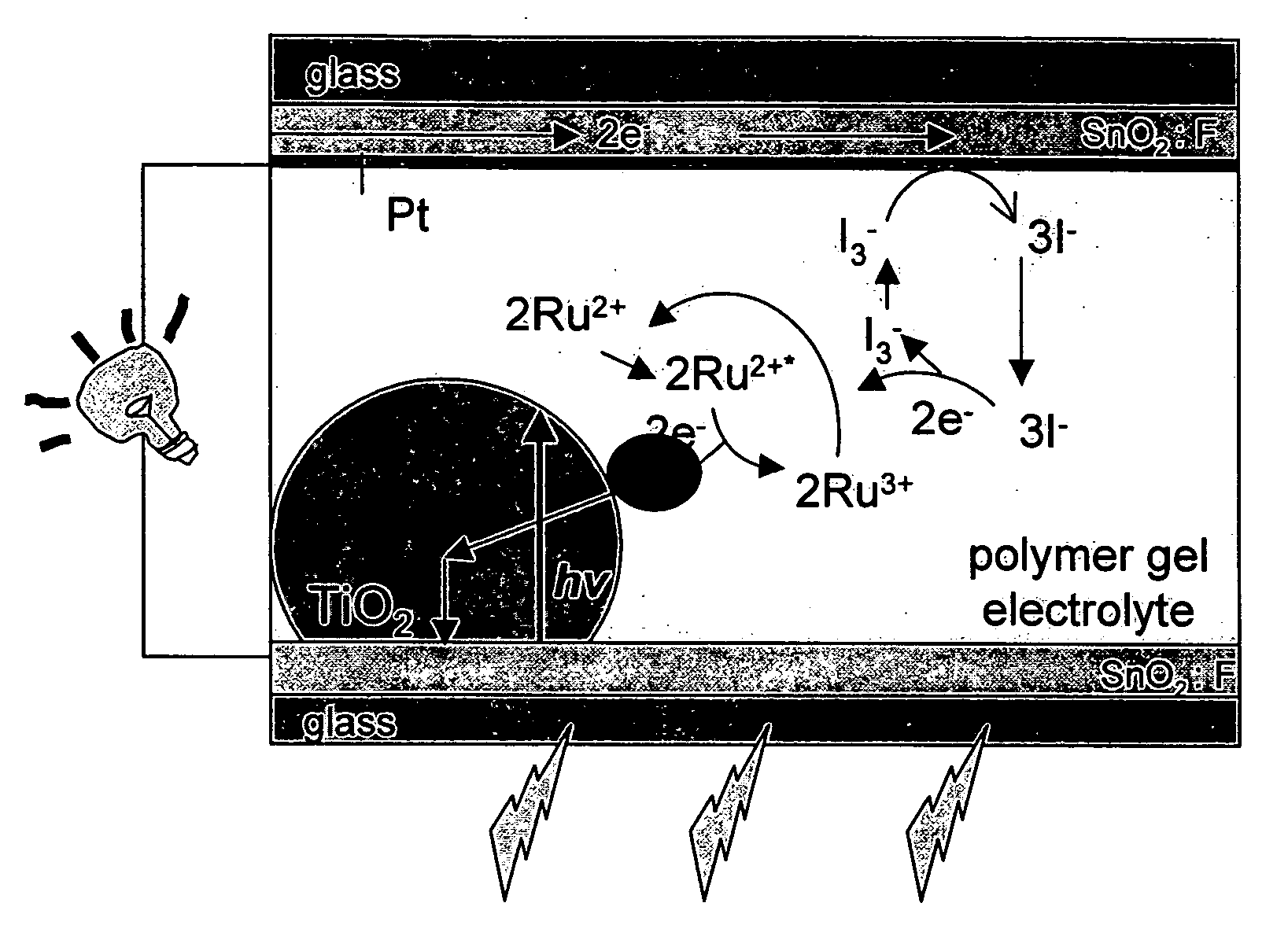
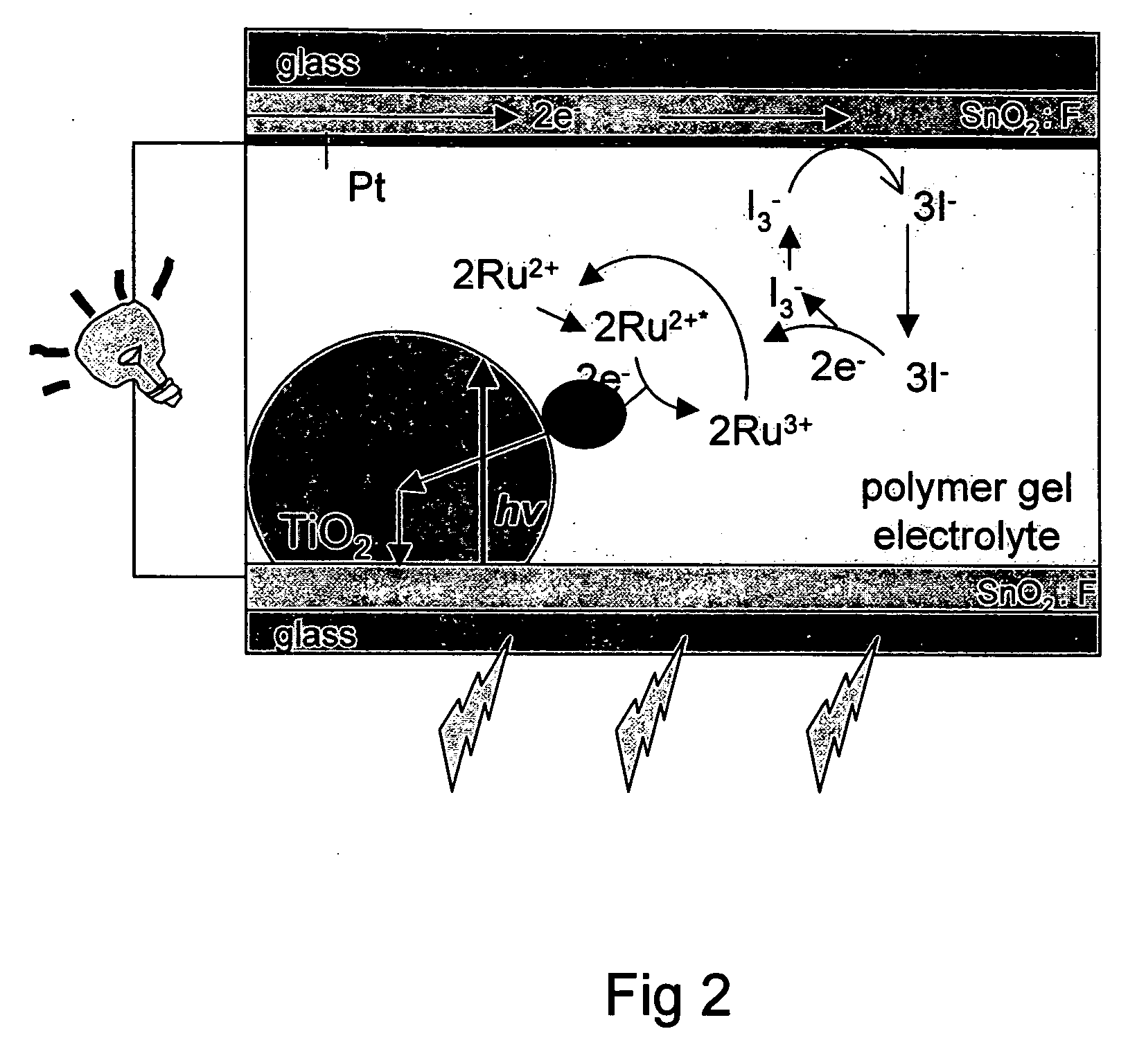
[0071] The electron transfer and transport processes in the cell are schematically shown in FIG. 2. Light absorbed by the dye molecules injects electrons in to TiO2 (t−10-12 s) and holes into the Li / I2 system (t−10−8 s). At the Pt back-electrode, the resulting I3− species will be reduced to I−, undergoing the following redox reactions [D. Kuciauskas, M. S. Freund, H. B. Gray, J. R. Winkler, and N. S. Lewis, J. Phys. Chem. B 105 (2001) 392][0072] 1) Ru(II)+hv→Ru(II)+[...


PUM


Abstract

A polymer gel hybrid solar cell which reach a light to energy conversion efficiency as high as 9.2% with 100 mW/cm2, and as high as 14.1% with reduced light intensity of 33 mW/cm2.

Description

BACKGROUND OF THE INVENTION [0001] The invention relates to a polymer gel hybrid solar cell comprising a polymer gel electrolyte. [0002] Single crystal solar cells show energy conversion efficiencies as high as ˜25%. Where the Si-based crystals are no longer single crystals but polycrystalline, the highest efficiencies are in the range of ˜18%, and with amorphous Si the efficiencies are ˜12%. Solar cells based on Si are, however, rather expensive to manufacture, even in the amorphous Si version. [0003] Therefore alternatives have been developed based on organic compounds and / or a mixture of organic and inorganic compounds, the latter type solar cells often being referred to as hybrid solar cells. Organic and hybrid solar cells have proved to be cheaper to manufacture, but seem to have comparably low efficiencies even when compared to amorphous Si cells. Due to their inherent advantages such as lightweight, low-cost fabrication of large areas, earth-friendly materials, or preparation...

Claims


Application Information

Patent Timeline
IPC IPC(8): H01G9/20H01L31/04H01L51/00H01L51/30H01M14/00
CPCH01G9/2009Y02E10/542H01L51/0086H01G9/2031H10K85/344H01L31/04H01G9/20
Inventor MITEVA, TZENKANELLES, GABRIELEYASUDA, AKIONODA, KAZUHIRO
Owner SONY DEUT GMBH
Why Eureka
Try Eureka