However, advances in the
semiconductor technology have lead to
switching power supplies, which are smaller and much more efficient compared to linear power supplies.
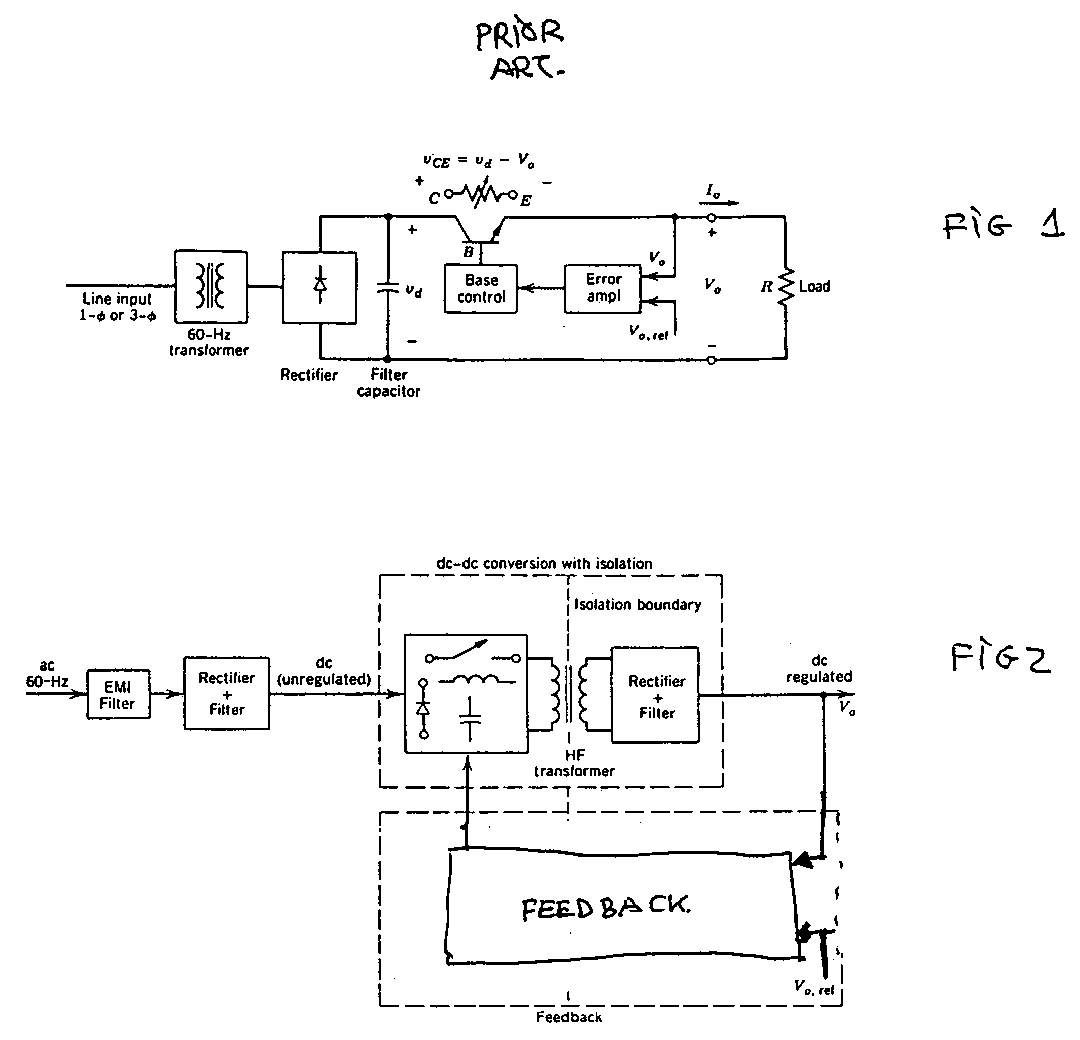
Linear power supplies suffer of two major drawbacks.
This represents a big penalty in the final size and weight of the power supply.
Since the
transistor operates in its active region, a significant amount of power is lost in it.
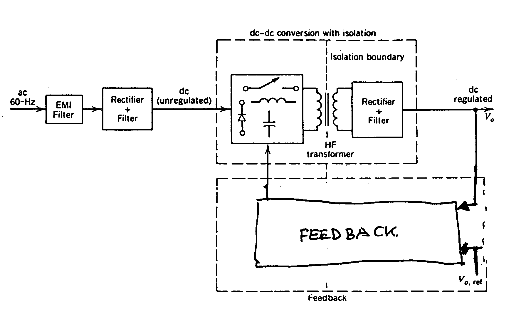
Since the power devices are not required to operate in their active region, this mode of operation results in lower power dissipation.
On the negative side,
switching power supplies suffer of the drawback of using magnetic transformers at very high frequencies.
Because a large number of turns of the conductor are required to realize a high
transformation ratio, electromagnetic transformers that are effective, yet at the same time compact and slim in shape are extremely difficult to produce.
In addition to being large in size and weight, wound transformers create EMI which can disrupt the performance of other circuits and components in proximity to the
transformer, which is a major issue in compact portable devices having a multitude of circuitry in a small packing area, such as
laptop computers, PDA's, camcorders, and other handheld devices.
Furthermore, in view of
high frequency applications and compact size application, the electromagnetic
transformer has many disadvantages related to the materials used in their manufacturing.
Magnetic materials used for the cores of transformers have two types of electrical losses,
eddy current loss due to finite electrical
conductivity and
hysteresis (magnetic) loss.
These windings are made from
copper wire, which
copper losses include not only
DC resistance loss, and additional ohmic loss caused by non-uniform
current density concentrations arising from the proximity effect and
skin effect.
Furthermore, wire-wound transformers also require winding isolation material, which also affects the final size of the component.
This is even a bigger issue in
high voltage transformers where
dielectric breakdown risk between high voltage and
low voltage wiring limits the minimum thickness of the isolation material used.
Furthermore, the maximum permissible temperature of a
transformer is approximately 100° C. and is limited by both magnetic material and winding isolation material considerations.
An inherent problem of such prior Rosen-PTs is that they have relatively low
power transmission capacity.
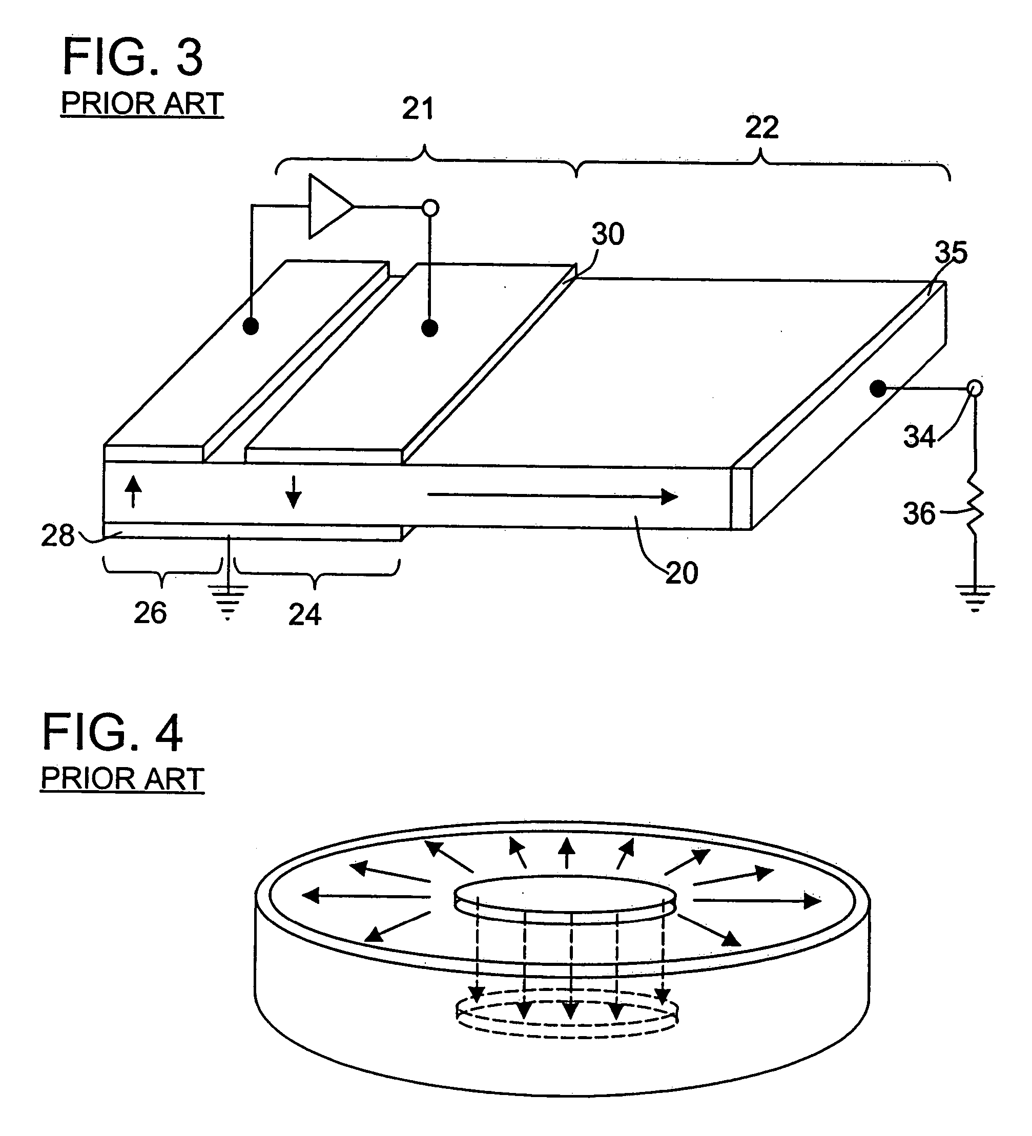
This
disadvantage of prior PTs relates to the fact that little or no
mechanical advantage is realized between the vibrator portion 21 of the device and the driver portion 22 of the device.
This inherently restricts the
mechanical energy transmission capability of the device, which, in turn, inherently restricts the electrical
power handling capacity of such devices.
As a result, Rosen-PTs show spurious bending resonances around the main
resonance frequency, specifically when thin bodies are used.
This bending
resonance may interfere with the main
resonance of the PT and thus diminish the efficiency of the PTs.
Additionally, the spurious bending resonance may affect the tracking circuitry of the Rosen-PT and may render the PT useless in practice.
Additionally, since the
transmitted power density is limited by the strain endurance of the piezoelectric material, Rosen-type PTs are limited in power to the maximum permissible tensile stresses in the
nodal transversal area, which is typically very small.
As consequence of this, Rosen-PTs become mechanically weak and may suffer fracture in the
nodal transversal area.
Another problem with prior Rosen PTs is that the input and output capacitances depend upon the total dimension of the
ceramic bar used.
Another drawback of conventional Rosen-type PTs is that since the
electrode of the high voltage section is located in the loop of vibration, i.e., in the vibrating direction, connection of the external terminals adversely affects vibration or largely degrades reliability.
An inherent problem with prior thickness mode PTs is that the thickness mode resonant frequency is too high for some applications.
Another problem with prior thickness mode PTs is the losses affecting the driving switching
inverter used to drive them, which limit the application of these PTs to high power applications.
Another problem with prior thickness mode PTs is their limitation to reach high output voltages, due to their thin thickness and low
output impedance, which leaves them out of the scope of the present invention.
A global problem of the prior state of the art of the
piezoelectric transformer technology is the impossibility of providing multiple outputs that may differ in their voltage and current rating.
In this prior state of the art, the
piezoelectric transformer has a limitation of providing a single output voltage to drive a specific load.
Thus, an inherent problem of the prior state of the art of power supplies using
piezoelectric transformer technology is the limitation to achieve very high voltages beyond the manufacturing possibilities of a
simple sample of PT.
Another problem of the prior state of the art of power supplies using piezoelectric transformer technology is the limitation to achieve very high power levels beyond the manufacturing possibilities of a
simple sample of PT.
Another problem of the prior state of the art of power supplies using piezoelectric transformer technology is the impossibility to provide at the same time high power and high voltage levels at the same time to the load.
Another limitation of the prior state of the art of power supplies using piezoelectric transformer technology is the impossibility of providing multiple outputs to drive different loads.
Another limitation of the prior state of the art of power supplies using piezoelectric transformer technology is the impossibility of providing multiple outputs which differ in their voltage and current rating.
Another limitation of the prior state of the art of power supplies using piezoelectric transformers technology is the impossibility of providing multiple outputs which are isolated from the input.

