Display apparatus

a liquid crystal display and display device technology, applied in the direction of diffusing elements, instruments, optical elements, etc., can solve the problems of insufficient vividness of images, inherently difficult to obtain high color purity, and insufficient vividness of colors, so as to achieve superior design, increase color reproducible range, and high emission efficiency

Inactive Publication Date: 2005-03-03
MITSUBISHI CHEM CORP
View PDF0 Cites 83 Cited by
  • Summary
  • Abstract
  • Description
  • Claims
  • Application Information

AI Technical Summary

Benefits of technology

An object of the present invention is to solve such problems, and this invention relates to a display device having a color filter, in which color reproducibility is considered to be extremely important, and relates to a technique of providing a display device in which while maintaining high emission efficiency, the color reproducible range is increased, and even while the display is not illuminated, no uncomfortableness is felt on the display screen, and which is superior in design.

Problems solved by technology

But if liquid crystal display devices are used for applications in which cathode-ray tubes have been mainly used, such as TV broadcasting, it has been pointed out that vividness of images is insufficient compared with cathode-ray tubes.
In particular, they are decisively inferior in vividness of colors, which is one of the most important properties as color display devices, compared with cathode-ray tubes.
As a suspected cause thereof, it can be pointed out that because color images are obtained by cutting specific spectra of the display light source with color filters, color purity is influenced by the characteristics of the light source and filters, as well as those of a polarizing plate and oriented film, so that it is inherently difficult to obtain high color purity compared with cathode-ray tubes and plasma displays in which light emission is obtained by simply exciting phosphor of each color of RGB (red / blue / green) by plasma discharge.
Due to such circumstances peculiar to liquid crystal panels, there was naturally a limit in the method in which color reproducibility is improved by a color filter having sharp spectral properties.
But because problems concerning endurance performance in the manufacturing steps and light resistance limit the color materials usable to coloring matters which are inferior in color reproducibility.
Thus, practically, it is extremely difficult to use color filters having sharp light transmitting properties.
In liquid crystal display devices, as described above, the problem is that the ability to reproduce brilliant colors is still insufficient compared with Cathode-ray tubes.
Thus, when images for which brilliant color reproducibility is required, such as landscape images, are displayed, they look poor.
But for liquid crystal display devices, since it is necessary to dispose such a filter function in a thin and lightweight back light source means, no method of simultaneously achieving uniformity of practical color purity, stability of yield and low cost has not yet been found.
Particularly in a side light type surface light source device, since only extremely thin space of not more than 5 mm in the total module thickness is available, in order to provide a filter function for cutting wavelengths positioned at intermediate points of the respective RGB colors in such extremely thin space, an extremely large number of problems arise.
This causes poor appearance frequently, thus lowering yield.
Especially if the size is large, it is seen as unevenness in color, and also, this markedly worsens optical efficiency (brightness).
As described above, if liquid crystal displays are used for displaying TV broadcasting or the like, for which cathode ray tubes have heretofore been mainly used, brilliance of images is insufficient compared with cathode ray tubes.
In particular, they are decisively inferior to cathode ray tubes in brilliance of color representation, which is one of the most important properties as color display devices.
One cause thereof is that an extremely complicated process is passed in which optical units for obtaining full color display for a liquid crystal display convert illuminating light from a discharge lamp represented by e.g. a cold cathode lamp to a surface light source, and specific spectra of the illuminating light source are cut by a color filter to obtain color images.
Properties of the light source, properties of the color filter, and properties of polarizing plates, oriented film, etc. get tangled in a complicated manner, thus influencing the color purity.
Thus, compared to cathode ray tubes and plasma displays, in which emissions are obtained simply by exciting phospher of the respective RGB (red, blue and green) colors by electron beams or plasma discharge, it is essentially difficult to obtain high color purity.
But in view of endurance performance in manufacturing steps and light resistance, it is extremely difficult to use dyes that are superior in wavelength cutting properties, as coloring materials particularly in an active matrix drive type panel.
Also, while filters using physico-optical phenomena such as interference filters and hologram filters are also superior in wavelength cutting properties, manufacturing steps are extremely complicated, so that they are not practical from an economical viewpoint.
After all, coloring materials usable are limited to the coloring matter family, which are inferior in wavelength cutting properties as shown in FIG. 43.
But normally, the band structures of phosphers are extremely complicated.
Thus it is not easy to design a phospher which emits only emission spectra corresponding purely to three colors, and frequently, as shown in FIG. 37, unintended emission spectra (sub-emissions) appear in wavelengths in intermediate portions of the respective wavelengths for three colors.
This causes further worsening of color reproducibility.
As it stands, the favorable feature of a liquid crystal display device that the consumed electric power is low and loads given to the environment is small will be impaired, so that this does not lead to an improved commercial value of the product.

Method used


Image

  • Display apparatus
  • Display apparatus
  • Display apparatus

Examples


example 1

(Example 1)

Using a biaxially stretched polyethylene terephthalate film (PET film made by Mitsubishi Polyester Film Corporation, thickness: 100 micrometers) as a substrate 31, in order to form a surface layer having light diffusibility, a coating liquid was prepared by mixing, into a 30 wt % toluene solution of polymethylmethacrylate resin (DIANAL BR-80 made by Mitsubishi Rayon Co., Ltd.), which is a binder resin, spherical beads having an average particle diameter of 27 micrometers and made of acrylic resin by 200 wt % with respect to the binder resin, diphenylsquarylium compound represented by a general formula (I-34) by 0.130 wt % with respect to the binder resin, and pyrazol-family squarylium compound expressed by a general formula (III-3) by 0.040 wt % with respect to the binder resin.

The coating liquid was applied by bar-coating method and dried. After uniformly applying it at a weighed amount of 5.4 g / m2 (as converted to the binder resin), the solvent was dried to obtain a ...

example 2

(Example 2)

Using a commercial iodine-family polarized film (transmittance: 44%, degree of polarization: 99.9%) as a substrate, a coating liquid was prepared by mixing a diphenyl squarylium-family compound expressed by formula (I-35) of [Chemical formula 2] and pyrazol-family squarylium compound expressed by formula (III-3) of [Chemical formula 13] by 0.190 wt % and 0.053 wt %, respectively, relative to the binder resin content into a 30 wt % toluene solution of polymethylmethacrylate resin (DIANAL BR-80 made by Mitsubishi Rayon) as the binder resin, and the coating liquid was applied by bar-coating method, and dried. After uniformly coating at a weighed amount of 5.4 g / m2 (converted to binder resin content), the solvent was dried to obtain a color material-dispersed layer of organic color materials.

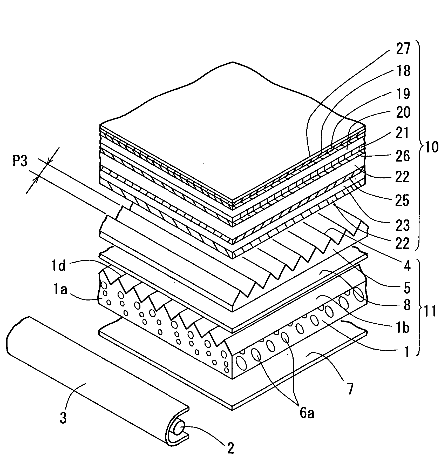
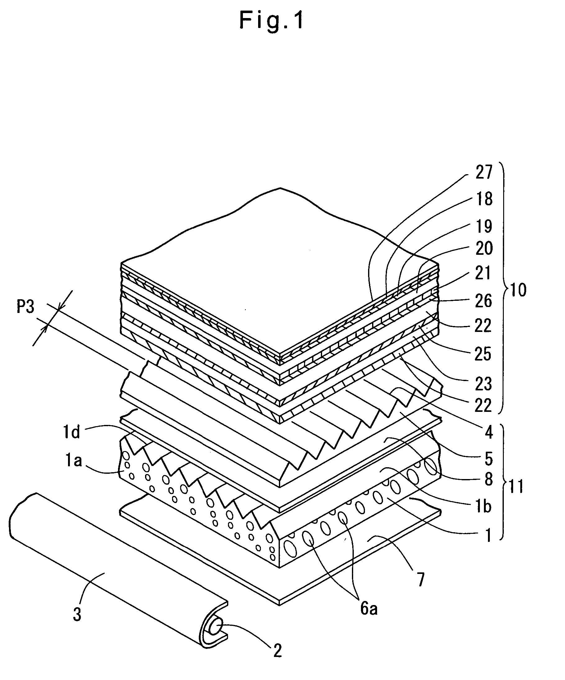
As shown in FIG. 1, the polarized film (sign 19) having the color material-dispersed layer (sign 18) was stuck on the front side of a transmission type active matrix-driven twisted nem...

example 3

(Example 3)

Using a biaxially oriented polyethylene terephthalate film (PET film made by Mitsubishi Polyester Film Corporation, thickness: 100 μm) as a substrate, in order to form a surface layer having a light-diffusing layer, a coating solution was prepared by mixing acrylic resin spherical beads having an average particle diameter of 35 μm, tetraazaporphyrin-family compound expressed by formula (II-1) of [Chemical formula 11], and pyrazol-family squarylium compound expressed by formula (III-3) of [Chemical formula 13] by 130 wt %, 0.105 wt % and 0.040 wt %, respectively, relative to a binder resin content into a 20 wt % dimethoxyethane solution of polymethyl methacrylate resin (DIANAL BR-80 made by Mitsubishi Rayon) as the binder resin.

The coating solution was coated by bar-coating method, dried. After uniformly coating at a weighed amount of 5.9 g / m2 (converted to binder resin content), the solvent was dried to obtain a color material-dispersed layer having light diffusion by ...


PUM

PropertyMeasurementUnit
thicknessaaaaaaaaaa
half band widthaaaaaaaaaa
light absorption half band widthaaaaaaaaaa

Abstract

In a display device having a color filter, a color material dispersed layer having the function of absorbing light of specific wavelengths in the visible light beam region is provided on the optical path so that the light absorption peak of this color material dispersed layer in the visible light beam region is located in the range of ±30 nm from the overlap point in the spectral transmission properties of each color of the color filter. Further, the color material dispersed layer is provided on a filter as a constituent part of the back light of the display. This filter has, as its substrate, a thermoplastic resin having a thickness of 30-350 micrometers and has a transmission in the maximum absorption wavelength in the color material dispersed layer of not more than 75%. The back light has, as its light source, a fluorescent lamp comprising a three band tube, and its emission color is subjected to color correction by an auxiliary filter having an organic color material dispersed layer provided on the illuminating light path.

Description

TECHNICAL FIELD TO WHICH THE PRESENT INVENTION BELONGS This invention relates to a novel liquid crystal display device that makes brilliant display possible, and particularly a liquid crystal display device that is extremely superior in color reproducibility and can be used for applications where cathode-ray tubes have been mainly used such as applications for TV broadcasting display. Also, the present invention relates to a film for a filter, a light condensing film and a polarized light film for improving the image properties of a liquid crystal display device, and a surface light source device using these films, and more specifically to a technique for providing a new illuminating optical system which increases color reproducibility of images in a liquid crystal display device. BACKGROUND OF THE INVENTION In recent years, as display devices such as monitors for personal computers and thin type TV's, many transmission type active matrix drive liquid crystal display devices are ...

Claims


Application Information

Patent Timeline
Patent Type & Authority Applications(United States)
IPC IPC(8): G02B5/02G02B5/20G02F1/1335G02F1/13357
CPCG02B5/0226G02B5/0242G02B5/0278G02B5/201G02B6/0041G02F2001/133607G02B6/0051G02B6/0053G02F1/133514G02F1/133604G02B6/0043G02F1/133607
Inventor SUGA, YOSHINORIOZAWA, TETSUOFUJIWARA, EISUKE
Owner MITSUBISHI CHEM CORP
Why Eureka
Try Eureka