Module incorporating a capacitor, method for manufacturing the same, and capacitor used therefor

a technology of capacitors and modules, applied in the direction of final product manufacturing, printed circuit non-printed electric components association, semiconductor/solid-state device details, etc., can solve the problems of physical damage, film-type solid-state capacitors are particularly difficult to handle as a single component, and the capacitors are particularly difficult to mount, so as to achieve the effect of reducing thickness and high density

Active Publication Date: 2005-04-07
PANASONIC CORP
View PDF20 Cites 42 Cited by
  • Summary
  • Abstract
  • Description
  • Claims
  • Application Information

AI Technical Summary

Benefits of technology

[0012] Therefore, in order to solve the above-described conventional problems, the present invention provides a module incorporating a capacitor capable of realizing miniaturization, a higher density and a reduced thickness and a method for producing the same, as well as a capacitor used for such a module.

Problems solved by technology

However, as the size and the thickness of the capacitors become increasingly small, the handling and the mounting of the capacitors have become particularly difficult.
However, the film-type solid electrolytic capacitor is particularly difficult to handle as a single component, since it is extremely thin although having a large capacitance.
Since such a film-type solid electrolytic capacitor generally has a thickness of 0.2 mm or less, it tends to be deformed by an external force and physically damaged.
Therefore, it has been difficult to mount on a substrate a single conventional capacitor unit, which is small and has weak mechanical strength, as a single component.
In the case of the film-type solid electrolytic capacitor, it has been particularly difficult to handle the capacitor as a single component, since it is small and very thin, with its thickness being 0.2 mm or less.
Furthermore, when such a film-type solid electrolytic capacitor is mounted onto a substrate as a single component, the functions of the capacitor may be damaged fatally by, for example, peeling of the surface layer.
Moreover, the surface layer is not flat, so that a sufficient suction force may not be obtained by vacuum suction and a suction failure or falling thus may occur during transporting the capacitor.
Therefore, it has been extremely difficult to perform a conventional automatic mounting.
However, in this case, the capacitor becomes large physically, and a plurality of capacitor units are concentrated on the same portion on the substrate, hindering the flexibility of the circuit design.
This results in the necessity to provide a more complex or longer wiring.
Therefore, in the case of using the conventional capacitor formed as a chip, it has been difficult to realize a further reduction in the size and the thickness of a module incorporating a capacitor.

Method used


Image

  • Module incorporating a capacitor, method for manufacturing the same, and capacitor used therefor
  • Module incorporating a capacitor, method for manufacturing the same, and capacitor used therefor
  • Module incorporating a capacitor, method for manufacturing the same, and capacitor used therefor

Examples


example 1

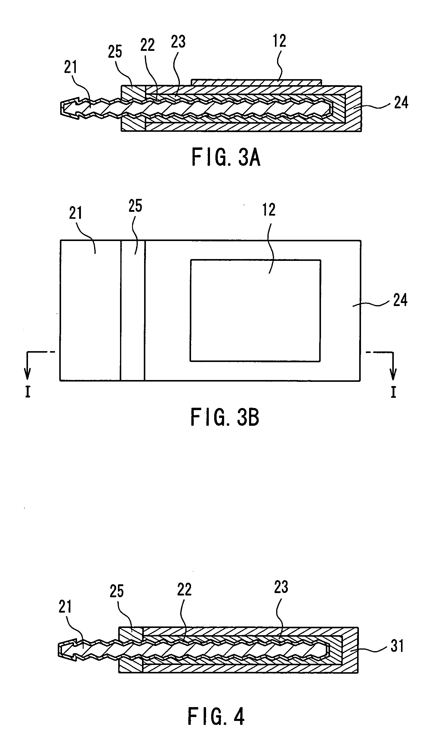
[0188] Example 1 of the present invention is a working example of the electrolytic capacitor component described in Embodiment 2 above. A solid electrolytic capacitor of the present example includes a foil-type ferromagnetic portion with an adhesive portion as the ferromagnetic portion, and has a configuration similar to that of the electrolytic capacitor component shown in FIG. 3.

[0189] First, an aluminum foil with a thickness of 100 μm was prepared as an anode valve metal, and the surface of the foil was roughened by electrolytic etching. The surface roughening was performed by applying an alternating current to the aluminum foil in an electrolyte containing hydrochloric acid as the main component at a concentration of 10 mass %, at a liquid temperature of 35° C. The roughened layer formed by the surface roughening had a thickness of about 40 μm. Then, the aluminum foil was cut into a 3 mm square region. The cut region was used as a capacitance forming portion.

[0190] Next, the a...

example 2

[0196] Example 2 of the present invention is a working example of the electrolytic capacitor component described in Embodiment 2 above. A solid electrolytic capacitor of the present example includes a particle-dispersed ferromagnetic portion as the ferromagnetic portion, and has a configuration similar to that of the electrolytic capacitor component shown in FIG. 3.

[0197] First, a paste mixture containing ferromagnetic particles was prepared by mixing 90 mass % of a powder of sendust (an alloy consisting of 5 mass % Al, 10 mass % Si and the remainder Fe) having an average particle size of 30 μm and serving as the ferromagnetic particles and 8 mass % of epoxy resin (“Epikote 828”, manufactured by Japan Epoxy Resins Co., Ltd.) and 2 mass % of a curing agent (“PN-23”, manufactured by Ajinomoto Fine-Techno Co., Inc) with three rolls.

[0198] The procedure of Example 1 was followed until after forming a cathode current collector, and then the paste mixture was printed by screen printing ...

example 3

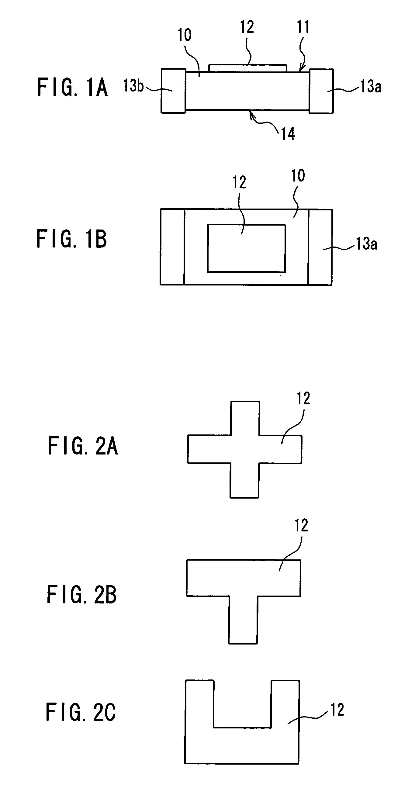
[0200] Example 3 of the present invention is a working example of the electrolytic capacitor component described in Embodiment 3 above. A solid electrolytic capacitor component of the present example includes a ferromagnetic current collector serving as both the cathode current collector and the ferromagnetic portion, and has a configuration similar to that of the electrolytic capacitor component shown in FIG. 2A.

[0201] First, a paste mixture was prepared by mixing 40 mass % of an Ag powder, 45 mass % of a powder of permalloy (alloy consisting of 45 mass % Ni and the remainder Fe) serving as the ferromagnetic particles and 15 mass % of an epoxy resin (including a curing agent) with three rolls. It should be noted that this paste mixture is the material that forms the ferromagnetic current collector, which serves both as the cathode current collector and the ferromagnetic portion in the solid electrolytic capacitor.

[0202] The procedure of Example 1 was followed to perform the surfa...


PUM

PropertyMeasurementUnit
thicknessaaaaaaaaaa
saturation flux densityaaaaaaaaaa
mass %aaaaaaaaaa

Abstract

A module incorporating a capacitor, the module including a circuit board and a layer incorporating a capacitor, wherein the circuit board includes a wiring layer and a via contact for providing electrical conductivity to a cathode and an anode of the capacitor. The layer incorporating the capacitor includes a ferromagnetic layer integrated with at least a portion of a surface of the capacitor, and in the circuit board or the layer incorporating the capacitor, a coil is wound around the capacitor, or an inductor component is disposed in parallel with the capacitor. Accordingly, a module incorporating a capacitor in which miniaturization, a higher density and a reduced thickness have been achieved, as well as a method for producing the module and a capacitor used for the module, are provided.

Description

BACKGROUND OF THE INVENTION [0001] 1. Field of the Invention [0002] The present invention relates to modules incorporating a capacitor, methods for manufacturing the same, and capacitors used therefor. [0003] 2. Description of the Related Art [0004] In recent years, with the progress in the miniaturization of various devices and the increase in density of capacitors constituting the devices, there is an increasing demand for the miniaturization of the capacitor itself. Moreover, with the development of higher speed devices, high-speed response and low-loss properties are demanded for capacitors equipped with a capacitor unit. In order to meet these demands, three-dimensional modules incorporating a capacitor in which a capacitor or a semiconductor component (active component) provided with a capacitor is incorporated in a substrate have been developed vigorously (see e.g., JP H11-220262A). [0005] At this time, in order to attain both a higher density and a reduced thickness for capa...

Claims


Application Information

Patent Timeline
Patent Type & Authority Applications(United States)
IPC IPC(8): H01G4/40H05K1/16H05K1/18H05K3/46
CPCH01G4/40H05K1/165H05K1/186H05K3/4614Y10T29/49155H05K2201/10015H05K2201/10636Y10T29/4913H05K2201/086Y02P70/50
Inventor HIRANO, KOICHIYOSHIDA, TSUNENORINAKATANI, SEIICHI
Owner PANASONIC CORP
Why Eureka
Try Eureka