Process for inhibiting SRZ formation and coating system therefor

a technology of coating system and srz, which is applied in the direction of superimposed coating process, solid-state diffusion coating, machines/engines, etc., can solve the problems of reducing the load-carrying capacity of alloys, complicated approaches proposed for further improving the spallation resistance of tbc's, and reducing the oxidation resistance. , to achieve the effect of reducing the incidence of srz

Inactive Publication Date: 2005-06-02
GENERAL ELECTRIC CO
View PDF19 Cites 35 Cited by
  • Summary
  • Abstract
  • Description
  • Claims
  • Application Information

AI Technical Summary

Benefits of technology

[0007] The present invention provides a process for significantly reducing the incidence of SRZ in

Problems solved by technology

Approaches proposed for further improving the spallation resistance of TBC's are complicated in part by the compositions of the underlying superalloy and interdiffusion that occurs between the superalloy and the bond coat.
The migration of elements across this interface alters the chemical composition and microstructure of both the bond coat and the substrate in the vicinity of the interface, generally with deleterious results.
For example, migrat

Method used


Image

  • Process for inhibiting SRZ formation and coating system therefor
  • Process for inhibiting SRZ formation and coating system therefor
  • Process for inhibiting SRZ formation and coating system therefor

Examples


Embodiment Construction

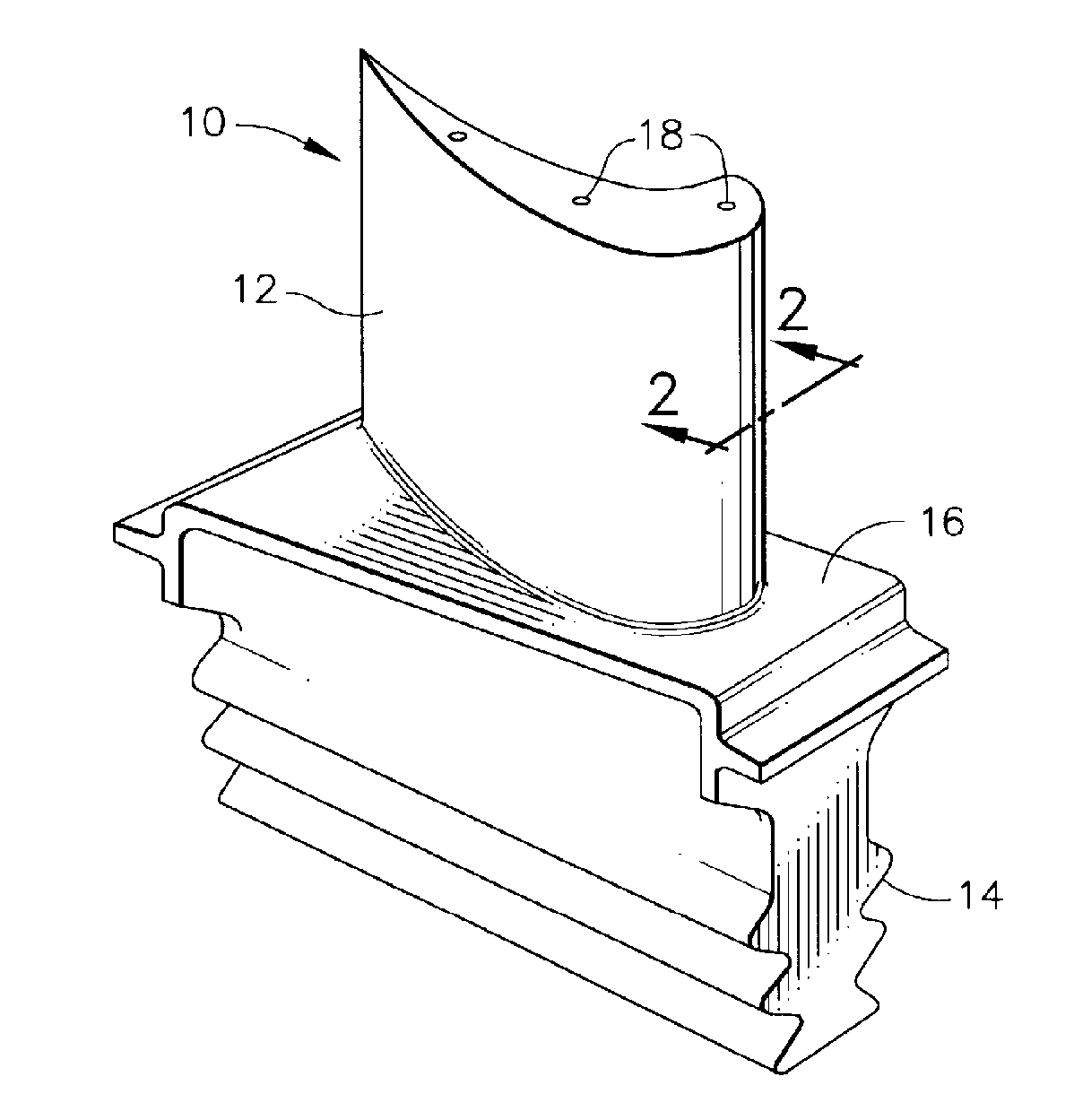
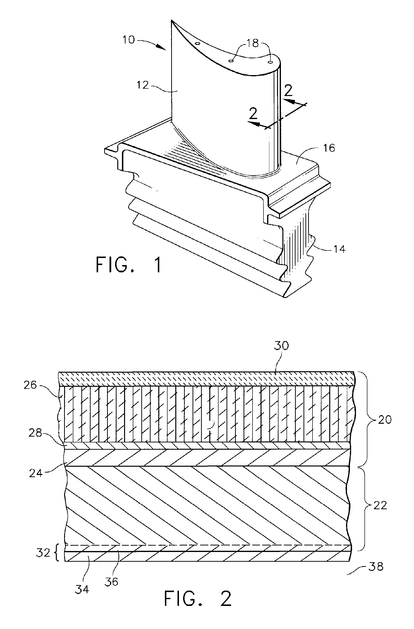
[0014] The present invention is intended for use on components that require coatings for protection from their operating environment. Notable examples of such components include the high and low pressure turbine nozzles and blades, shrouds, combustor liners and augmentor hardware of gas turbine engines. An example of a high pressure turbine blade 10 is shown in FIG. 1. The blade 10 generally includes an airfoil 12 against which hot combustion gases are directed during operation of the gas turbine engine, and whose surface is therefore subjected to severe attack by oxidation, corrosion and erosion. The airfoil 12 is anchored to a turbine disk (not shown) with a dovetail 14 formed on a root section 16 of the blade 10. Cooling holes 18 are present in the airfoil 12 through which bleed air flowing through internal passages (not shown) within the blade 10 exits to transfer heat from the blade 10. While the advantages of this invention will be described with reference to components of a g...


PUM

PropertyMeasurementUnit
Fractionaaaaaaaaaa
Fractionaaaaaaaaaa
Fractionaaaaaaaaaa

Abstract

A process for reducing the incidence of a secondary reaction zone (SRZ) in alloys prone to SRZ formation, particularly superalloys that have a high refractory element content. The process finds use with articles having a wall region that defines external and internal surfaces on the exterior and within the article, respectively. Diffusion coatings are formed on the internal and external surfaces of the article, with at least the diffusion coating on the external surface comprising an additive layer and a diffusion zone that is beneath the additive layer and extends into the wall region. The additive layer and at least a portion of the diffusion zone of the external diffusion coating is then removed to define an exposed surface region on the exterior of the article. An overlay coating is then deposited on the exposed surface region.

Description

BACKGROUND OF THE INVENTION [0001] The present invention generally relates to protective coating systems for components exposed to high temperatures, such as the hostile thermal environment of a gas turbine engine. More particularly, this invention relates to a process for inhibiting the formation of a secondary reaction zone (SRZ) in a substrate on which such a coating system is deposited. [0002] Certain turbine, combustor and augmentor components of gas turbine engines are susceptible to damage by oxidation and hot corrosion attack, and are therefore protected by an environmental coating and optionally a thermal barrier coating (TBC), in which case the environmental coating is termed a bond coat. In combination, the TBC and bond coat form what has been termed a TBC system. [0003] Environmental coatings and TBC bond coats are often formed of an oxidation-resistant aluminum-containing alloy or intermetallic. An example of the former is MCrAlX (where M is iron, cobalt and / or nickel, ...

Claims


Application Information

Patent Timeline
IPC IPC(8): C23C10/60C23C16/00C23C22/74C23C28/00C23F1/20C23F1/44F01D5/28
CPCC23C10/60C23C22/74C23C28/3215C23C28/345C23C28/3455C23F1/20C23C28/36F01D5/288F05D2230/90F05D2300/611C23C28/321C23C28/34C23C28/341C23F1/44
Inventor GORMAN, MARK DANIELBRUCE, ROBERT WILLIAM
Owner GENERAL ELECTRIC CO
Why Eureka
Try Eureka