Voltage-controlled oscillator, clock converter, and electronic device

a voltage-controlled oscillator and clock converter technology, applied in the direction of heat measurement, optical radiation measurement, instruments, etc., can solve the problems voltage-controlled saw oscillator has the problem of requiring a wider frequency variable range, and the necessary frequency variable range is decreased, so as to achieve stable data transmission and reception, maintain high accuracy, and reduce unnecessary jitter

Inactive Publication Date: 2005-06-09
SEIKO EPSON CORP
View PDF3 Cites 31 Cited by
  • Summary
  • Abstract
  • Description
  • Claims
  • Application Information

AI Technical Summary

Benefits of technology

[0062] With the above structure, the frequency variable range can be compensated even at a narrow control voltage width and as such, the frequency deviation of the converted clock signals can be maintained highly accurate. Accordingly, a timing margin can be assured between the transmission / reception data and clock signals according to clock signals, in which unnecessary jitter has been significantly reduced even when clock signals having a large amount of jitter are inputted. Thus, electronic devices incorporating the clock converter according to the present invention, such as an optical transceiver module, can perform stable data transmission and reception via an optical network over a wide ambient temperature without malfunctioning. Furthermore, since a clock converter is provided, which uses the micro-miniaturized and low-price voltage-controlled oscillator which requires no dedicated temperature compensator circuit for correcting the frequency temperature characteristic of the SAW resonator, the optical transceiver module can be advantageously reduced in size and price.

Problems solved by technology

As shown in FIG. 25, the conventional SAW resonator has a larger fluctuation in frequency deviation with respect to the temperature change than that of the AT quartz crystal resonator, thus having the problem of requiring a wider frequency variable range of the voltage-controlled SAW oscillator than that of the voltage-controlled quartz crystal oscillator.
(2) The voltage-controlled SAW oscillator has the problem of requiring a wider frequency variable range than that for the voltage-controlled quartz crystal oscillator to compensate the system accuracy due to frequency fluctuations caused by itself.
When the supply voltage is lowered, the control voltage for varying the frequency of the clock signal cannot be greatly varied, thus the necessary frequency variable range is decreased and a possibility of not satisfying the specification of the system accuracy exists.
This is also the problem that prevents the requirement for increasing the specification of the system accuracy from being met.
This problem is common to both the voltage-controlled SAW oscillator and the voltage-controlled quartz crystal oscillator.
Particularly, the voltage-controlled SAW oscillator has such large self-caused frequency fluctuation that it is difficult to ensure the frequency variable range, thus preventing the system accuracy from being met.
(4) The conventional voltage-controlled oscillators (VCOs) and clock converters using the same have increased in size because of the characteristic and structure, thus having the problem that they cannot respond to the recent requirements for micro-miniaturization and low cost.
Consequently, the coupling of the unnecessary vibrations, the unnecessary unwanted mode caused by the AT quartz crystal resonator and the unnecessary harmonic waves generated by the multiplexer circuit 82 become the cause of jitter, thus posing the problem of increasing the jitter of outputted clock signals.
Therefore, the increase of the number of components disadvantageously increases the size of the voltage-controlled oscillator.
This produces the possibility of increasing the size of the clock converter, as in the above.

Method used


Image

  • Voltage-controlled oscillator, clock converter, and electronic device
  • Voltage-controlled oscillator, clock converter, and electronic device
  • Voltage-controlled oscillator, clock converter, and electronic device

Examples


first embodiment

[0091] A first embodiment will be described at first.

[0092] (1) Structure of the Embodiment

[0093] Structure of Voltage-Controlled SAW Oscillator

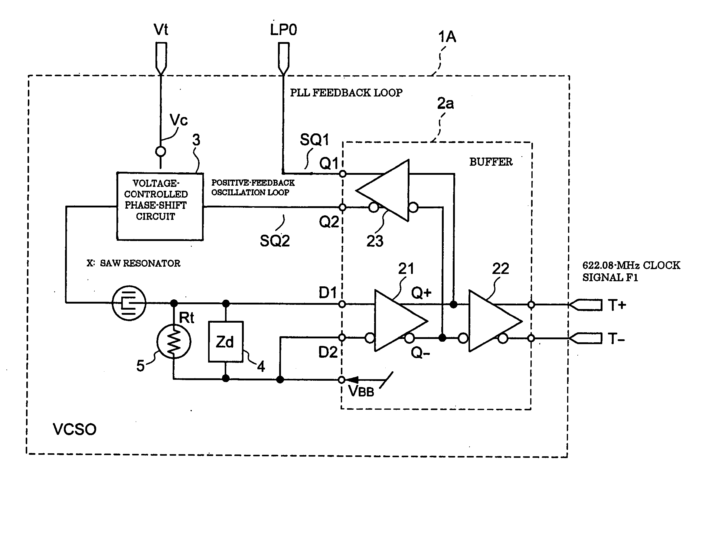
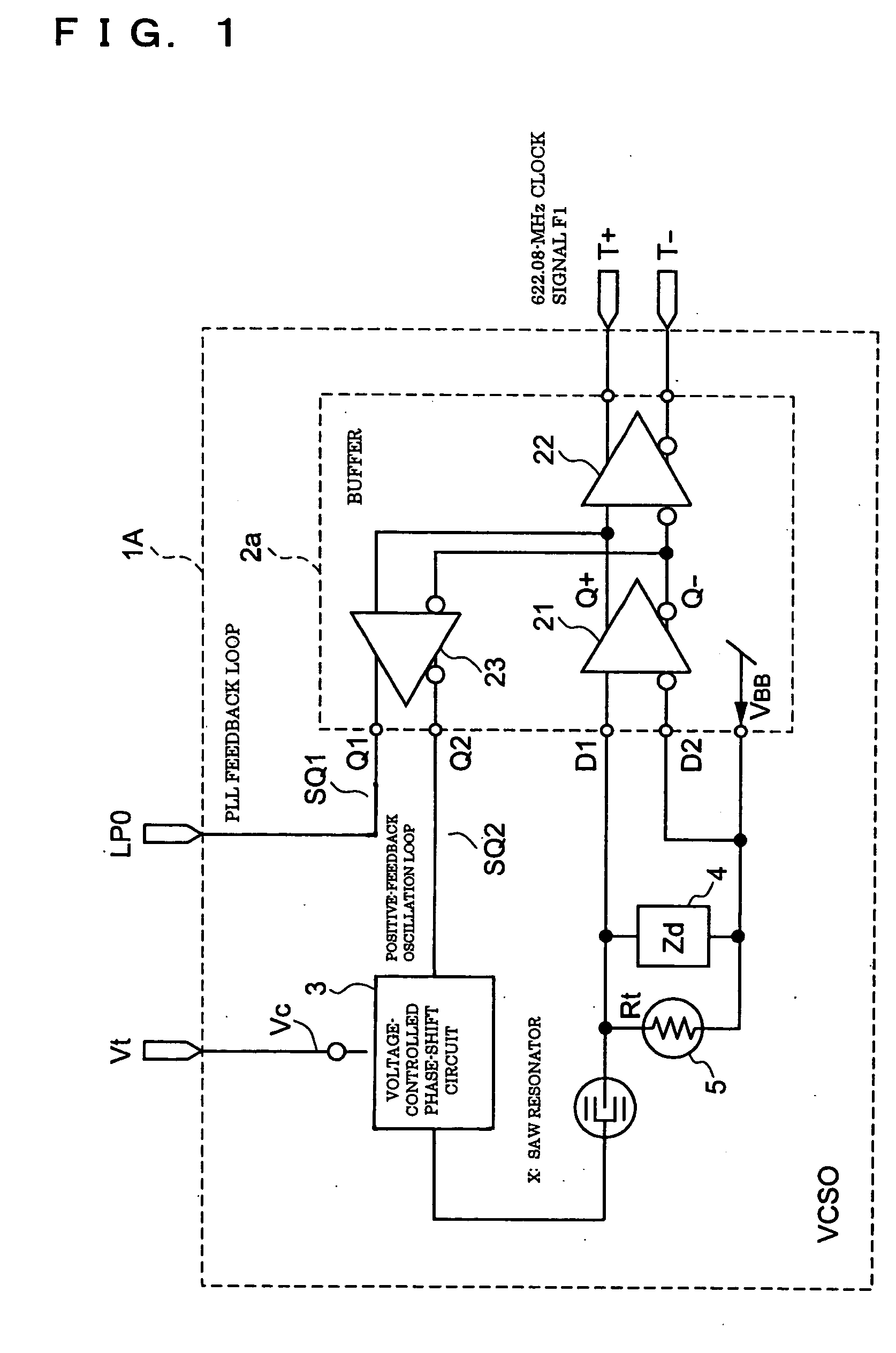
[0094]FIG. 1 is a block diagram of a voltage-controlled SAW oscillator 1A. The voltage-controlled SAW oscillator 1A includes a buffer 2a having three differential amplifiers 21, 22, and 23 built in, a SAW resonator X which resonates at a specified frequency, a voltage-controlled phase-shift circuit 3 for shifting the phase of the oscillation signal by a specified amount according to an external control voltage Vc to vary the resonance frequency of the SAW resonator X, an impedance circuit (Zd) 4, and an NTC thermistor (Rt) 5 is connected to the impedance circuit (Zd) 4 in parallel. At least the oscillating differential amplifier (first differential amplifier) 21, the feedback-buffer differential amplifier (second differential amplifier) 23, the voltage-controlled phase-shift circuit 3, and the SAW resonator X form a positive-feedback osci...

second embodiment

[0144] A second embodiment will now be described.

[0145]FIG. 17 is a block diagram of a voltage-controlled SAW oscillator (VCSO) 1B according to the second embodiment.

[0146] The difference from FIG. 1 is to use an amplifier having a single input / output in place of the differential amplifier. More specifically, a plurality of amplifiers 32-1 to 32-n and 33 are connected to the output of an oscillating amplifier 31 in parallel, and used as the feedback buffer amplifier 33 forming a positive-feedback oscillation loop and the output amplifiers 32-1 to 32-n being used to output signals to the outside.

[0147] Referring to FIG. 17, a buffer 2b uses the amplifiers 31, 32-1 to 32-n, and 33 each having a single input / output in place of the differential amplifiers shown in FIG. 1. The plurality of amplifiers 32-1 to 32-n and the feedback buffer amplifier (second amplifier) 32 are connected to the output stage of the oscillating amplifier (first amplifier) 31 in parallel. The oscillating ampli...

third embodiment

[0153] A third embodiment will now be described.

[0154]FIG. 18 is a block diagram of a clock converter according to the third embodiment.

[0155] In this embodiment, a clock converter incorporating the voltage-controlled SAW oscillator 1A described in the first embodiment will be described. The clock converter is characterized in that the feedback-loop output terminal LP0 of the voltage-controlled SAW oscillator 1A using the SAW resonator X, improved in a frequency temperature characteristic, is used to form a feedback loop. More specifically, any of the plurality of output signals of the feedback-buffer differential amplifier 23 constructing the voltage-controlled SAW oscillator 1A, shown in FIG. 1, is used as a feedback-loop output signal.

[0156] A clock converter 50a shown in FIG. 18 includes a phase comparing section 55, a loop filter (LPF) 53, and the voltage-controlled SAW oscillator 1A. The phase comparing section 55 includes an input frequency divider circuit (division ratio:...


PUM


Abstract

A voltage-controlled oscillator includes a voltage-controlled phase-shift circuit, outputting a signal with the shift deviated from an input signal by a specified amount with an external control voltage Vt, a SAW resonator, a buffer, inputting a resonance signal having a specified resonance frequency from the SAW resonator, outputting a clock signal with a desired frequency, and outputting a positive-feedback-oscillation-loop output signal, wherein the voltage-controlled phase-shift circuit, the SAW resonator, and the buffer construct a positive-feedback oscillation loop, in which the frequency temperature characteristic of the SAW resonator is rotated by a specified amount using the temperature characteristic of the propagation delay time of the buffer to correct the frequency temperature characteristic of the SAW resonator.

Description

BACKGROUND [0001] 1. Technical Field to which the Invention Belongs [0002] The present invention relates to a voltage-controlled oscillator, a clock converter, and an electronic device and, more specifically, it relates to a voltage-controlled oscillator using a SAW resonator and having little frequency fluctuations caused by itself, a clock converter for converting a fundamental clock signal on the order of several kHz (e.g. 8 kHz) to a high-frequency clock signal of several hundred MHz (e.g. 622.08 MHz), and an electronic device using the clock converter. [0003] 2. Related Art [0004] Communication equipment such as cellular phones transmits and receives communication data according to clock signals from oscillators. Market requirements have shifted to a high frequency band exceeding 400 MHz with an increasing trend to broadband communication networks. Data are now transmitted and received in this high frequency band. From the demand for higher communication speed, as for the recen...

Claims


Application Information

Patent Timeline
Patent Type & Authority Applications(United States)
IPC IPC(8): H03B5/30H03B5/04H03B5/18H03B5/32H03B5/36H03B7/12H03H9/25H03L7/099H04J3/06H04L7/00
CPCH03B5/04H03B5/326H04L7/0091H03L7/099H04J3/0685H03B5/368
Inventor OGISO, HIROYUKI
Owner SEIKO EPSON CORP
Why Eureka
Try Eureka